

1 Introduction of Aptamer, SELEX, and Different SELEX Variants
9
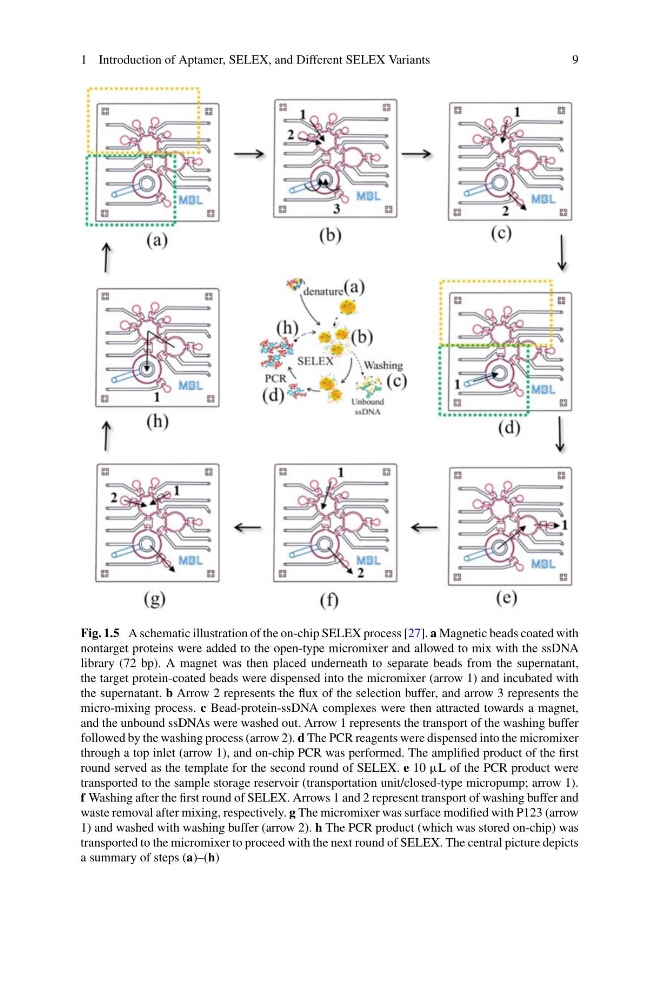
Fig. 1.5 A schematic illustration of the on-chip SELEX process [27]. a Magnetic beads coated with
nontarget proteins were added to the open-type micromixer and allowed to mix with the ssDNA
library (72 bp). A magnet was then placed underneath to separate beads from the supernatant,
the target protein-coated beads were dispensed into the micromixer (arrow 1) and incubated with
the supernatant. b Arrow 2 represents the flux of the selection buffer, and arrow 3 represents the
micro-mixing process. c Bead-protein-ssDNA complexes were then attracted towards a magnet,
and the unbound ssDNAs were washed out. Arrow 1 represents the transport of the washing buffer
followed by the washing process (arrow 2). d The PCR reagents were dispensed into the micromixer
through a top inlet (arrow 1), and on-chip PCR was performed. The amplified product of the first
round served as the template for the second round of SELEX. e 10 μL of the PCR product were
transported to the sample storage reservoir (transportation unit/closed-type micropump; arrow 1).
f Washing after the first round of SELEX. Arrows 1 and 2 represent transport of washing buffer and
waste removal after mixing, respectively. g The micromixer was surface modified with P123 (arrow
1) and washed with washing buffer (arrow 2). h The PCR product (which was stored on-chip) was
transported to the micromixer to proceed with the next round of SELEX. The central picture depicts
a summary of steps (a)–(h)
9
Fig. 1.5 A schematic illustration of the on-chip SELEX process [27]. a Magnetic beads coated with
nontarget proteins were added to the open-type micromixer and allowed to mix with the ssDNA
library (72 bp). A magnet was then placed underneath to separate beads from the supernatant,
the target protein-coated beads were dispensed into the micromixer (arrow 1) and incubated with
the supernatant. b Arrow 2 represents the flux of the selection buffer, and arrow 3 represents the
micro-mixing process. c Bead-protein-ssDNA complexes were then attracted towards a magnet,
and the unbound ssDNAs were washed out. Arrow 1 represents the transport of the washing buffer
followed by the washing process (arrow 2). d The PCR reagents were dispensed into the micromixer
through a top inlet (arrow 1), and on-chip PCR was performed. The amplified product of the first
round served as the template for the second round of SELEX. e 10 μL of the PCR product were
transported to the sample storage reservoir (transportation unit/closed-type micropump; arrow 1).
f Washing after the first round of SELEX. Arrows 1 and 2 represent transport of washing buffer and
waste removal after mixing, respectively. g The micromixer was surface modified with P123 (arrow
1) and washed with washing buffer (arrow 2). h The PCR product (which was stored on-chip) was
transported to the micromixer to proceed with the next round of SELEX. The central picture depicts
a summary of steps (a)–(h)