

50
S. Conrad et al.
of the tool side to close a circuit between the two rods of the “female side” (Fig. 1C top)
the presence or absence of a tool can be detected.
In addition to a fan to cool the hot end, most filaments require a second fan that blows
directly onto the extruded filament to accelerate solidification. This fan is located on the
print-head as well, but in contrast to its temperature control it is only needed while the
tool is in use.
That makes it possible to power the fan by utilizing the other coupling connections
as + and − pole (Fig. 1C bottom). By this, the control of the print fan is independent of
the active tool, eliminating the need to occupy additional slots on the controller board
and simplifying the program code.
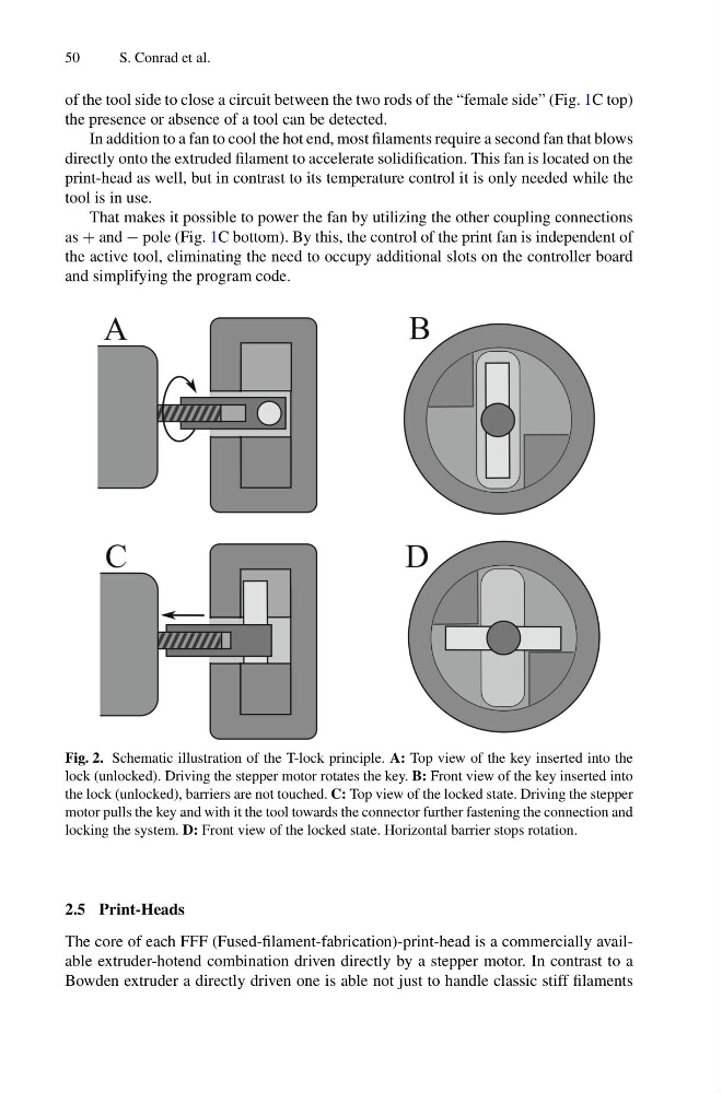
Fig. 2. Schematic illustration of the T-lock principle. A: Top view of the key inserted into the
lock (unlocked). Driving the stepper motor rotates the key. B: Front view of the key inserted into
the lock (unlocked), barriers are not touched. C: Top view of the locked state. Driving the stepper
motor pulls the key and with it the tool towards the connector further fastening the connection and
locking the system. D: Front view of the locked state. Horizontal barrier stops rotation.
2.5 Print-Heads
The core of each FFF (Fused-filament-fabrication)-print-head is a commercially available extruder-hotend combination driven directly by a stepper motor. In contrast to a
Bowden extruder a directly driven one is able not just to handle classic stiff filaments
S. Conrad et al.
of the tool side to close a circuit between the two rods of the “female side” (Fig. 1C top)
the presence or absence of a tool can be detected.
In addition to a fan to cool the hot end, most filaments require a second fan that blows
directly onto the extruded filament to accelerate solidification. This fan is located on the
print-head as well, but in contrast to its temperature control it is only needed while the
tool is in use.
That makes it possible to power the fan by utilizing the other coupling connections
as + and − pole (Fig. 1C bottom). By this, the control of the print fan is independent of
the active tool, eliminating the need to occupy additional slots on the controller board
and simplifying the program code.
Fig. 2. Schematic illustration of the T-lock principle. A: Top view of the key inserted into the
lock (unlocked). Driving the stepper motor rotates the key. B: Front view of the key inserted into
the lock (unlocked), barriers are not touched. C: Top view of the locked state. Driving the stepper
motor pulls the key and with it the tool towards the connector further fastening the connection and
locking the system. D: Front view of the locked state. Horizontal barrier stops rotation.
2.5 Print-Heads
The core of each FFF (Fused-filament-fabrication)-print-head is a commercially available extruder-hotend combination driven directly by a stepper motor. In contrast to a
Bowden extruder a directly driven one is able not just to handle classic stiff filaments