

Multi-material 3D-Printer for Rapid Prototyping
49
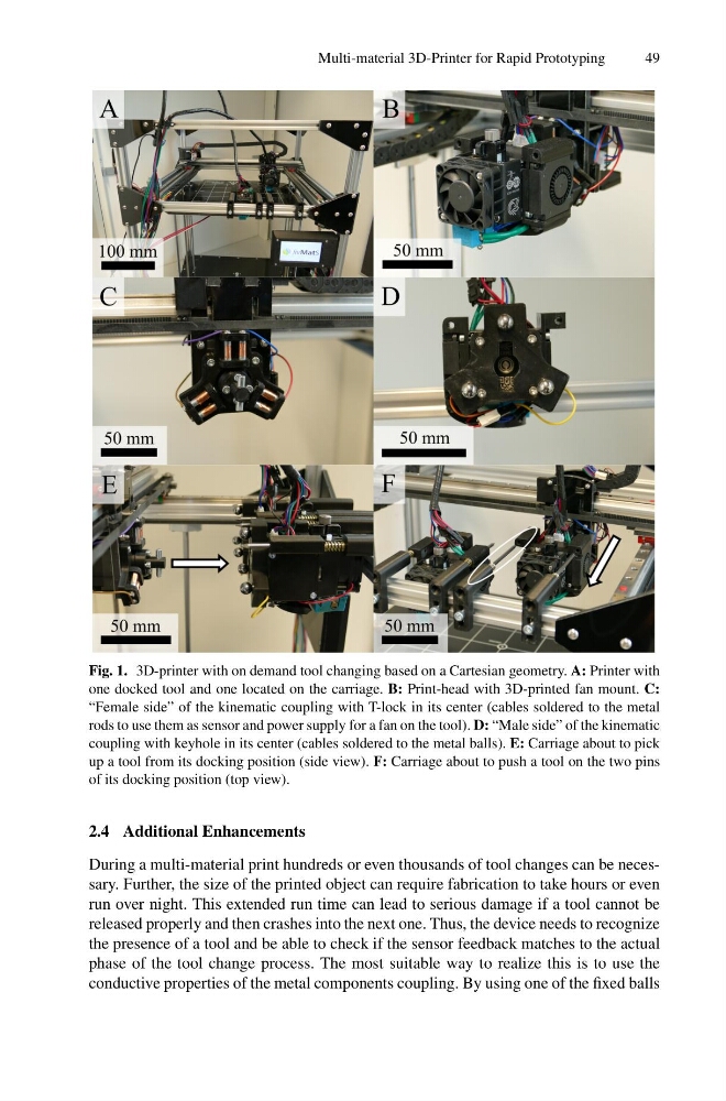
Fig. 1. 3D-printer with on demand tool changing based on a Cartesian geometry. A: Printer with
one docked tool and one located on the carriage. B: Print-head with 3D-printed fan mount. C:
“Female side” of the kinematic coupling with T-lock in its center (cables soldered to the metal
rods to use them as sensor and power supply for a fan on the tool). D: “Male side” of the kinematic
coupling with keyhole in its center (cables soldered to the metal balls). E: Carriage about to pick
up a tool from its docking position (side view). F: Carriage about to push a tool on the two pins
of its docking position (top view).
2.4 Additional Enhancements
During a multi-material print hundreds or even thousands of tool changes can be necessary. Further, the size of the printed object can require fabrication to take hours or even
run over night. This extended run time can lead to serious damage if a tool cannot be
released properly and then crashes into the next one. Thus, the device needs to recognize
the presence of a tool and be able to check if the sensor feedback matches to the actual
phase of the tool change process. The most suitable way to realize this is to use the
conductive properties of the metal components coupling. By using one of the fixed balls
49
Fig. 1. 3D-printer with on demand tool changing based on a Cartesian geometry. A: Printer with
one docked tool and one located on the carriage. B: Print-head with 3D-printed fan mount. C:
“Female side” of the kinematic coupling with T-lock in its center (cables soldered to the metal
rods to use them as sensor and power supply for a fan on the tool). D: “Male side” of the kinematic
coupling with keyhole in its center (cables soldered to the metal balls). E: Carriage about to pick
up a tool from its docking position (side view). F: Carriage about to push a tool on the two pins
of its docking position (top view).
2.4 Additional Enhancements
During a multi-material print hundreds or even thousands of tool changes can be necessary. Further, the size of the printed object can require fabrication to take hours or even
run over night. This extended run time can lead to serious damage if a tool cannot be
released properly and then crashes into the next one. Thus, the device needs to recognize
the presence of a tool and be able to check if the sensor feedback matches to the actual
phase of the tool change process. The most suitable way to realize this is to use the
conductive properties of the metal components coupling. By using one of the fixed balls