

418
L. Zhu et al.
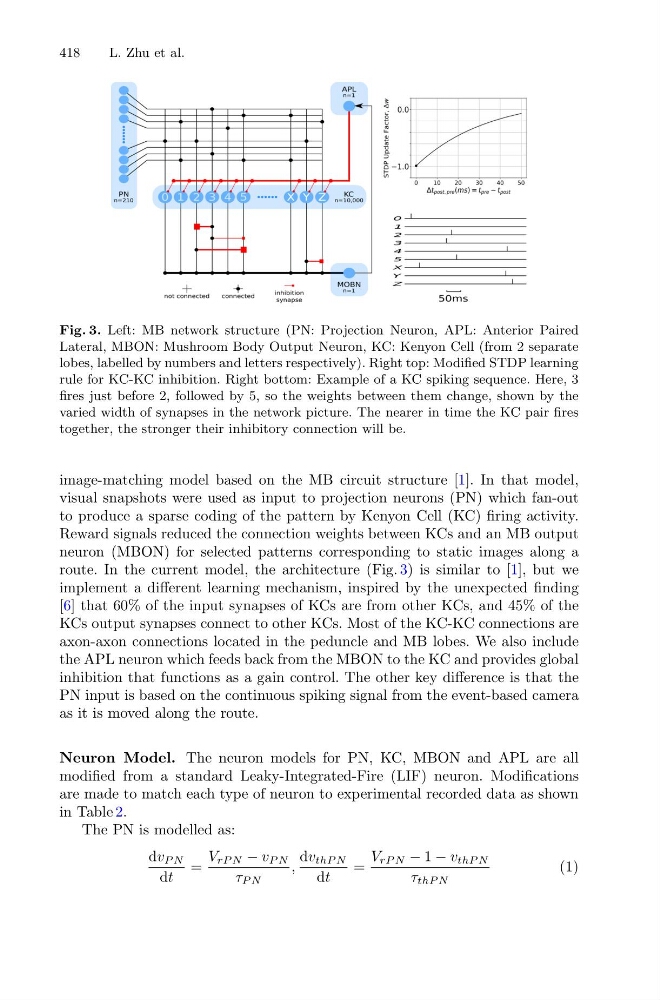
Fig. 3. Left: MB network structure (PN: Projection Neuron, APL: Anterior Paired
Lateral, MBON: Mushroom Body Output Neuron, KC: Kenyon Cell (from 2 separate
lobes, labelled by numbers and letters respectively). Right top: Modified STDP learning
rule for KC-KC inhibition. Right bottom: Example of a KC spiking sequence. Here, 3
fires just before 2, followed by 5, so the weights between them change, shown by the
varied width of synapses in the network picture. The nearer in time the KC pair fires
together, the stronger their inhibitory connection will be.
image-matching model based on the MB circuit structure [1]. In that model,
visual snapshots were used as input to projection neurons (PN) which fan-out
to produce a sparse coding of the pattern by Kenyon Cell (KC) firing activity.
Reward signals reduced the connection weights between KCs and an MB output
neuron (MBON) for selected patterns corresponding to static images along a
route. In the current model, the architecture (Fig. 3) is similar to [1], but we
implement a different learning mechanism, inspired by the unexpected finding
[6] that 60% of the input synapses of KCs are from other KCs, and 45% of the
KCs output synapses connect to other KCs. Most of the KC-KC connections are
axon-axon connections located in the peduncle and MB lobes. We also include
the APL neuron which feeds back from the MBON to the KC and provides global
inhibition that functions as a gain control. The other key difference is that the
PN input is based on the continuous spiking signal from the event-based camera
as it is moved along the route.
Neuron Model. The neuron models for PN, KC, MBON and APL are all
modified from a standard Leaky-Integrated-Fire (LIF) neuron. Modifications
are made to match each type of neuron to experimental recorded data as shown
in Table 2.
The PN is modelled as:
dv P N
dt
=
V rP N − v P N
τ P N
,
dv thP N
dt
=
V rP N − 1 − v thP N
τ thP N
(1)
L. Zhu et al.
Fig. 3. Left: MB network structure (PN: Projection Neuron, APL: Anterior Paired
Lateral, MBON: Mushroom Body Output Neuron, KC: Kenyon Cell (from 2 separate
lobes, labelled by numbers and letters respectively). Right top: Modified STDP learning
rule for KC-KC inhibition. Right bottom: Example of a KC spiking sequence. Here, 3
fires just before 2, followed by 5, so the weights between them change, shown by the
varied width of synapses in the network picture. The nearer in time the KC pair fires
together, the stronger their inhibitory connection will be.
image-matching model based on the MB circuit structure [1]. In that model,
visual snapshots were used as input to projection neurons (PN) which fan-out
to produce a sparse coding of the pattern by Kenyon Cell (KC) firing activity.
Reward signals reduced the connection weights between KCs and an MB output
neuron (MBON) for selected patterns corresponding to static images along a
route. In the current model, the architecture (Fig. 3) is similar to [1], but we
implement a different learning mechanism, inspired by the unexpected finding
[6] that 60% of the input synapses of KCs are from other KCs, and 45% of the
KCs output synapses connect to other KCs. Most of the KC-KC connections are
axon-axon connections located in the peduncle and MB lobes. We also include
the APL neuron which feeds back from the MBON to the KC and provides global
inhibition that functions as a gain control. The other key difference is that the
PN input is based on the continuous spiking signal from the event-based camera
as it is moved along the route.
Neuron Model. The neuron models for PN, KC, MBON and APL are all
modified from a standard Leaky-Integrated-Fire (LIF) neuron. Modifications
are made to match each type of neuron to experimental recorded data as shown
in Table 2.
The PN is modelled as:
dv P N
dt
=
V rP N − v P N
τ P N
,
dv thP N
dt
=
V rP N − 1 − v thP N
τ thP N
(1)