

372
S. C. van den Berg et al.
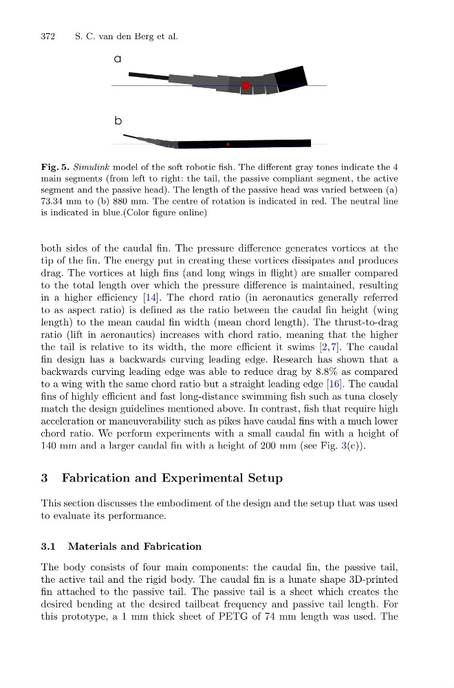
Fig. 5. Simulink model of the soft robotic fish. The different gray tones indicate the 4
main segments (from left to right: the tail, the passive compliant segment, the active
segment and the passive head). The length of the passive head was varied between (a)
73.34 mm to (b) 880 mm. The centre of rotation is indicated in red. The neutral line
is indicated in blue.(Color figure online)
both sides of the caudal fin. The pressure difference generates vortices at the
tip of the fin. The energy put in creating these vortices dissipates and produces
drag. The vortices at high fins (and long wings in flight) are smaller compared
to the total length over which the pressure difference is maintained, resulting
in a higher efficiency [14]. The chord ratio (in aeronautics generally referred
to as aspect ratio) is defined as the ratio between the caudal fin height (wing
length) to the mean caudal fin width (mean chord length). The thrust-to-drag
ratio (lift in aeronautics) increases with chord ratio, meaning that the higher
the tail is relative to its width, the more efficient it swims [2,7]. The caudal
fin design has a backwards curving leading edge. Research has shown that a
backwards curving leading edge was able to reduce drag by 8.8% as compared
to a wing with the same chord ratio but a straight leading edge [16]. The caudal
fins of highly efficient and fast long-distance swimming fish such as tuna closely
match the design guidelines mentioned above. In contrast, fish that require high
acceleration or maneuverability such as pikes have caudal fins with a much lower
chord ratio. We perform experiments with a small caudal fin with a height of
140 mm and a larger caudal fin with a height of 200 mm (see Fig. 3(c)).
3 Fabrication and Experimental Setup
This section discusses the embodiment of the design and the setup that was used
to evaluate its performance.
3.1 Materials and Fabrication
The body consists of four main components: the caudal fin, the passive tail,
the active tail and the rigid body. The caudal fin is a lunate shape 3D-printed
fin attached to the passive tail. The passive tail is a sheet which creates the
desired bending at the desired tailbeat frequency and passive tail length. For
this prototype, a 1 mm thick sheet of PETG of 74 mm length was used. The
S. C. van den Berg et al.
Fig. 5. Simulink model of the soft robotic fish. The different gray tones indicate the 4
main segments (from left to right: the tail, the passive compliant segment, the active
segment and the passive head). The length of the passive head was varied between (a)
73.34 mm to (b) 880 mm. The centre of rotation is indicated in red. The neutral line
is indicated in blue.(Color figure online)
both sides of the caudal fin. The pressure difference generates vortices at the
tip of the fin. The energy put in creating these vortices dissipates and produces
drag. The vortices at high fins (and long wings in flight) are smaller compared
to the total length over which the pressure difference is maintained, resulting
in a higher efficiency [14]. The chord ratio (in aeronautics generally referred
to as aspect ratio) is defined as the ratio between the caudal fin height (wing
length) to the mean caudal fin width (mean chord length). The thrust-to-drag
ratio (lift in aeronautics) increases with chord ratio, meaning that the higher
the tail is relative to its width, the more efficient it swims [2,7]. The caudal
fin design has a backwards curving leading edge. Research has shown that a
backwards curving leading edge was able to reduce drag by 8.8% as compared
to a wing with the same chord ratio but a straight leading edge [16]. The caudal
fins of highly efficient and fast long-distance swimming fish such as tuna closely
match the design guidelines mentioned above. In contrast, fish that require high
acceleration or maneuverability such as pikes have caudal fins with a much lower
chord ratio. We perform experiments with a small caudal fin with a height of
140 mm and a larger caudal fin with a height of 200 mm (see Fig. 3(c)).
3 Fabrication and Experimental Setup
This section discusses the embodiment of the design and the setup that was used
to evaluate its performance.
3.1 Materials and Fabrication
The body consists of four main components: the caudal fin, the passive tail,
the active tail and the rigid body. The caudal fin is a lunate shape 3D-printed
fin attached to the passive tail. The passive tail is a sheet which creates the
desired bending at the desired tailbeat frequency and passive tail length. For
this prototype, a 1 mm thick sheet of PETG of 74 mm length was used. The