

328
J. Stankiewicz and B. Webb
.x
ground
speed
Farneback
optic flow
Matched
filter
Weight
matrix
Ground
height (h)
θ
Timestamped
Image
sequence
a
preprocess
W1 = h
W2 = h/sinθ
h
b
c
e
g
d
f
h
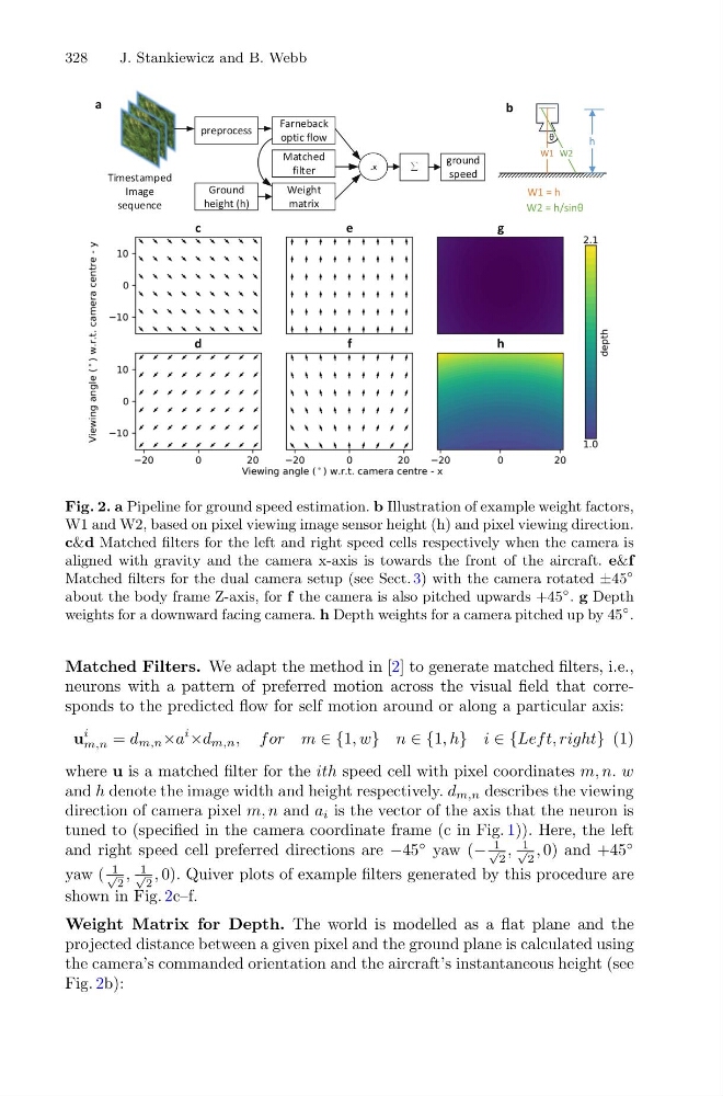
Fig. 2. a Pipeline for ground speed estimation. b Illustration of example weight factors,
W1 and W2, based on pixel viewing image sensor height (h) and pixel viewing direction.
c&d Matched filters for the left and right speed cells respectively when the camera is
aligned with gravity and the camera x-axis is towards the front of the aircraft. e&f
Matched filters for the dual camera setup (see Sect. 3) with the camera rotated ±45
◦
about the body frame Z-axis, for f the camera is also pitched upwards +45
◦ . g Depth
weights for a downward facing camera. h Depth weights for a camera pitched up by 45
◦ .
Matched Filters. We adapt the method in [2] to generate matched filters, i.e.,
neurons with a pattern of preferred motion across the visual field that corresponds to the predicted flow for self motion around or along a particular axis:
u
i
m,n = d m,n ×a
i
×d m,n , for m ∈ {1, w} n ∈ {1, h} i ∈ {Lef t, right} (1)
where u is a matched filter for the ith speed cell with pixel coordinates m, n. w
and h denote the image width and height respectively. d m,n describes the viewing
direction of camera pixel m, n and a i is the vector of the axis that the neuron is
tuned to (specified in the camera coordinate frame (c in Fig. 1)). Here, the left
and right speed cell preferred directions are −45
◦ yaw (−
1
√
2
,
1
√
2
, 0) and +45
◦
yaw (
1
√
2
,
1
√
2
, 0). Quiver plots of example filters generated by this procedure are
shown in Fig. 2c–f.
Weight Matrix for Depth. The world is modelled as a flat plane and the
projected distance between a given pixel and the ground plane is calculated using
the camera’s commanded orientation and the aircraft’s instantaneous height (see
Fig. 2b):
J. Stankiewicz and B. Webb
.x
ground
speed
Farneback
optic flow
Matched
filter
Weight
matrix
Ground
height (h)
θ
Timestamped
Image
sequence
a
preprocess
W1 = h
W2 = h/sinθ
h
b
c
e
g
d
f
h
Fig. 2. a Pipeline for ground speed estimation. b Illustration of example weight factors,
W1 and W2, based on pixel viewing image sensor height (h) and pixel viewing direction.
c&d Matched filters for the left and right speed cells respectively when the camera is
aligned with gravity and the camera x-axis is towards the front of the aircraft. e&f
Matched filters for the dual camera setup (see Sect. 3) with the camera rotated ±45
◦
about the body frame Z-axis, for f the camera is also pitched upwards +45
◦ . g Depth
weights for a downward facing camera. h Depth weights for a camera pitched up by 45
◦ .
Matched Filters. We adapt the method in [2] to generate matched filters, i.e.,
neurons with a pattern of preferred motion across the visual field that corresponds to the predicted flow for self motion around or along a particular axis:
u
i
m,n = d m,n ×a
i
×d m,n , for m ∈ {1, w} n ∈ {1, h} i ∈ {Lef t, right} (1)
where u is a matched filter for the ith speed cell with pixel coordinates m, n. w
and h denote the image width and height respectively. d m,n describes the viewing
direction of camera pixel m, n and a i is the vector of the axis that the neuron is
tuned to (specified in the camera coordinate frame (c in Fig. 1)). Here, the left
and right speed cell preferred directions are −45
◦ yaw (−
1
√
2
,
1
√
2
, 0) and +45
◦
yaw (
1
√
2
,
1
√
2
, 0). Quiver plots of example filters generated by this procedure are
shown in Fig. 2c–f.
Weight Matrix for Depth. The world is modelled as a flat plane and the
projected distance between a given pixel and the ground plane is calculated using
the camera’s commanded orientation and the aircraft’s instantaneous height (see
Fig. 2b):