

Robophysical Modeling of Soft Limbless Locomotors
305
damped; if it stopped self-deforming, it rapidly stopped translating (see analysis
of a similar propulsion scheme in [19]).
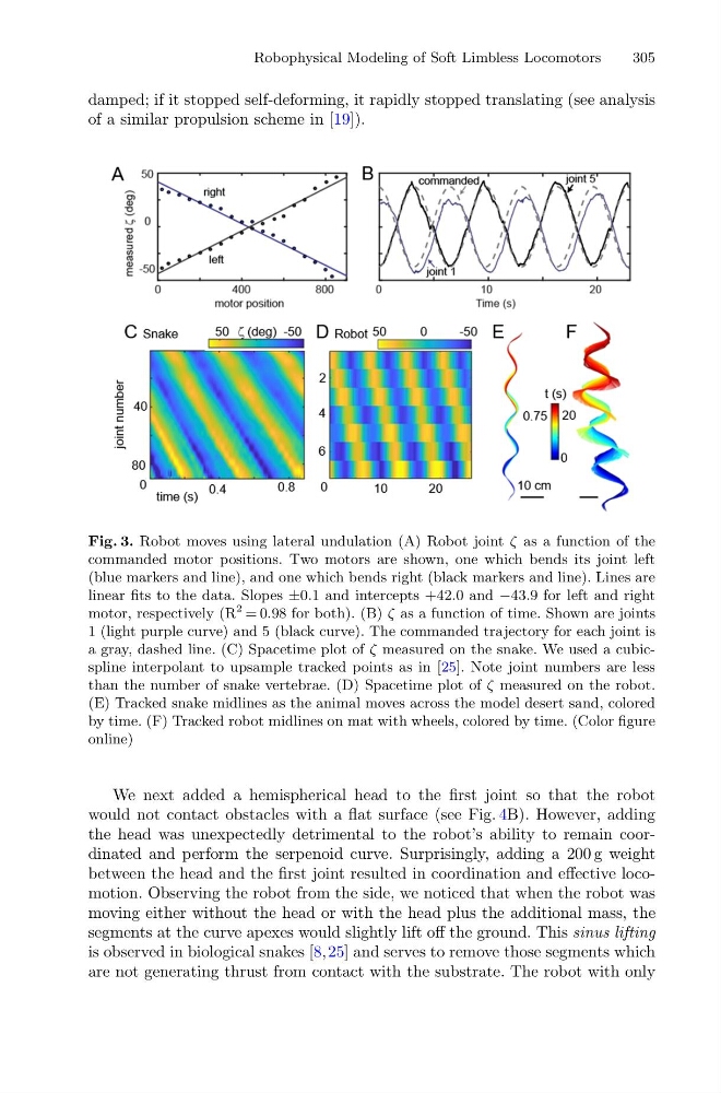
Fig. 3. Robot moves using lateral undulation (A) Robot joint ζ as a function of the
commanded motor positions. Two motors are shown, one which bends its joint left
(blue markers and line), and one which bends right (black markers and line). Lines are
linear fits to the data. Slopes ±0.1 and intercepts +42.0 and −43.9 for left and right
motor, respectively (R
2 = 0.98 for both). (B) ζ as a function of time. Shown are joints
1 (light purple curve) and 5 (black curve). The commanded trajectory for each joint is
a gray, dashed line. (C) Spacetime plot of ζ measured on the snake. We used a cubicspline interpolant to upsample tracked points as in [25]. Note joint numbers are less
than the number of snake vertebrae. (D) Spacetime plot of ζ measured on the robot.
(E) Tracked snake midlines as the animal moves across the model desert sand, colored
by time. (F) Tracked robot midlines on mat with wheels, colored by time. (Color figure
online)
We next added a hemispherical head to the first joint so that the robot
would not contact obstacles with a flat surface (see Fig. 4B). However, adding
the head was unexpectedly detrimental to the robot’s ability to remain coordinated and perform the serpenoid curve. Surprisingly, adding a 200 g weight
between the head and the first joint resulted in coordination and effective locomotion. Observing the robot from the side, we noticed that when the robot was
moving either without the head or with the head plus the additional mass, the
segments at the curve apexes would slightly lift off the ground. This sinus lifting
is observed in biological snakes [8,25] and serves to remove those segments which
are not generating thrust from contact with the substrate. The robot with only
305
damped; if it stopped self-deforming, it rapidly stopped translating (see analysis
of a similar propulsion scheme in [19]).
Fig. 3. Robot moves using lateral undulation (A) Robot joint ζ as a function of the
commanded motor positions. Two motors are shown, one which bends its joint left
(blue markers and line), and one which bends right (black markers and line). Lines are
linear fits to the data. Slopes ±0.1 and intercepts +42.0 and −43.9 for left and right
motor, respectively (R
2 = 0.98 for both). (B) ζ as a function of time. Shown are joints
1 (light purple curve) and 5 (black curve). The commanded trajectory for each joint is
a gray, dashed line. (C) Spacetime plot of ζ measured on the snake. We used a cubicspline interpolant to upsample tracked points as in [25]. Note joint numbers are less
than the number of snake vertebrae. (D) Spacetime plot of ζ measured on the robot.
(E) Tracked snake midlines as the animal moves across the model desert sand, colored
by time. (F) Tracked robot midlines on mat with wheels, colored by time. (Color figure
online)
We next added a hemispherical head to the first joint so that the robot
would not contact obstacles with a flat surface (see Fig. 4B). However, adding
the head was unexpectedly detrimental to the robot’s ability to remain coordinated and perform the serpenoid curve. Surprisingly, adding a 200 g weight
between the head and the first joint resulted in coordination and effective locomotion. Observing the robot from the side, we noticed that when the robot was
moving either without the head or with the head plus the additional mass, the
segments at the curve apexes would slightly lift off the ground. This sinus lifting
is observed in biological snakes [8,25] and serves to remove those segments which
are not generating thrust from contact with the substrate. The robot with only