

304
P. E. Schiebel et al.
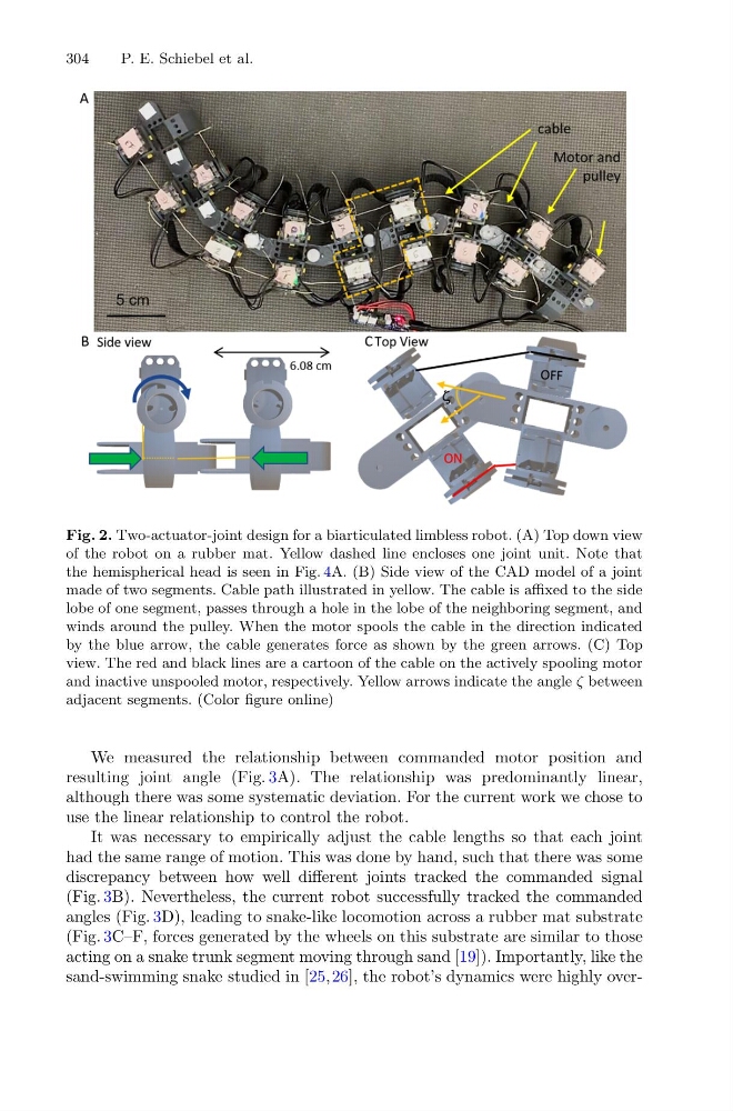
Fig. 2. Two-actuator-joint design for a biarticulated limbless robot. (A) Top down view
of the robot on a rubber mat. Yellow dashed line encloses one joint unit. Note that
the hemispherical head is seen in Fig. 4A. (B) Side view of the CAD model of a joint
made of two segments. Cable path illustrated in yellow. The cable is affixed to the side
lobe of one segment, passes through a hole in the lobe of the neighboring segment, and
winds around the pulley. When the motor spools the cable in the direction indicated
by the blue arrow, the cable generates force as shown by the green arrows. (C) Top
view. The red and black lines are a cartoon of the cable on the actively spooling motor
and inactive unspooled motor, respectively. Yellow arrows indicate the angle ζ between
adjacent segments. (Color figure online)
We measured the relationship between commanded motor position and
resulting joint angle (Fig. 3A). The relationship was predominantly linear,
although there was some systematic deviation. For the current work we chose to
use the linear relationship to control the robot.
It was necessary to empirically adjust the cable lengths so that each joint
had the same range of motion. This was done by hand, such that there was some
discrepancy between how well different joints tracked the commanded signal
(Fig. 3B). Nevertheless, the current robot successfully tracked the commanded
angles (Fig. 3D), leading to snake-like locomotion across a rubber mat substrate
(Fig. 3C–F, forces generated by the wheels on this substrate are similar to those
acting on a snake trunk segment moving through sand [19]). Importantly, like the
sand-swimming snake studied in [25,26], the robot’s dynamics were highly over-
P. E. Schiebel et al.
Fig. 2. Two-actuator-joint design for a biarticulated limbless robot. (A) Top down view
of the robot on a rubber mat. Yellow dashed line encloses one joint unit. Note that
the hemispherical head is seen in Fig. 4A. (B) Side view of the CAD model of a joint
made of two segments. Cable path illustrated in yellow. The cable is affixed to the side
lobe of one segment, passes through a hole in the lobe of the neighboring segment, and
winds around the pulley. When the motor spools the cable in the direction indicated
by the blue arrow, the cable generates force as shown by the green arrows. (C) Top
view. The red and black lines are a cartoon of the cable on the actively spooling motor
and inactive unspooled motor, respectively. Yellow arrows indicate the angle ζ between
adjacent segments. (Color figure online)
We measured the relationship between commanded motor position and
resulting joint angle (Fig. 3A). The relationship was predominantly linear,
although there was some systematic deviation. For the current work we chose to
use the linear relationship to control the robot.
It was necessary to empirically adjust the cable lengths so that each joint
had the same range of motion. This was done by hand, such that there was some
discrepancy between how well different joints tracked the commanded signal
(Fig. 3B). Nevertheless, the current robot successfully tracked the commanded
angles (Fig. 3D), leading to snake-like locomotion across a rubber mat substrate
(Fig. 3C–F, forces generated by the wheels on this substrate are similar to those
acting on a snake trunk segment moving through sand [19]). Importantly, like the
sand-swimming snake studied in [25,26], the robot’s dynamics were highly over-