

252
S. Meyer et al.
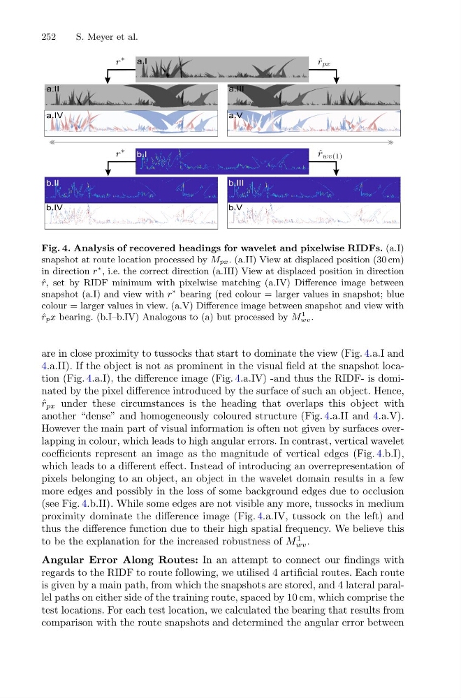
Fig. 4. Analysis of recovered headings for wavelet and pixelwise RIDFs. (a.I)
snapshot at route location processed by Mpx. (a.II) View at displaced position (30 cm)
in direction r
∗ , i.e. the correct direction (a.III) View at displaced position in direction
ˆ
r, set by RIDF minimum with pixelwise matching (a.IV) Difference image between
snapshot (a.I) and view with r
∗ bearing (red colour = larger values in snapshot; blue
colour = larger values in view. (a.V) Difference image between snapshot and view with
ˆ
rpx bearing. (b.I–b.IV) Analogous to (a) but processed by M
1
wv .
are in close proximity to tussocks that start to dominate the view (Fig. 4.a.I and
4.a.II). If the object is not as prominent in the visual field at the snapshot location (Fig. 4.a.I), the difference image (Fig. 4.a.IV) -and thus the RIDF- is dominated by the pixel difference introduced by the surface of such an object. Hence,
ˆ
r px under these circumstances is the heading that overlaps this object with
another “dense” and homogeneously coloured structure (Fig. 4.a.II and 4.a.V).
However the main part of visual information is often not given by surfaces overlapping in colour, which leads to high angular errors. In contrast, vertical wavelet
coefficients represent an image as the magnitude of vertical edges (Fig. 4.b.I),
which leads to a different effect. Instead of introducing an overrepresentation of
pixels belonging to an object, an object in the wavelet domain results in a few
more edges and possibly in the loss of some background edges due to occlusion
(see Fig. 4.b.II). While some edges are not visible any more, tussocks in medium
proximity dominate the difference image (Fig. 4.a.IV, tussock on the left) and
thus the difference function due to their high spatial frequency. We believe this
to be the explanation for the increased robustness of M
1
wv .
Angular Error Along Routes: In an attempt to connect our findings with
regards to the RIDF to route following, we utilised 4 artificial routes. Each route
is given by a main path, from which the snapshots are stored, and 4 lateral parallel paths on either side of the training route, spaced by 10 cm, which comprise the
test locations. For each test location, we calculated the bearing that results from
comparison with the route snapshots and determined the angular error between
S. Meyer et al.
Fig. 4. Analysis of recovered headings for wavelet and pixelwise RIDFs. (a.I)
snapshot at route location processed by Mpx. (a.II) View at displaced position (30 cm)
in direction r
∗ , i.e. the correct direction (a.III) View at displaced position in direction
ˆ
r, set by RIDF minimum with pixelwise matching (a.IV) Difference image between
snapshot (a.I) and view with r
∗ bearing (red colour = larger values in snapshot; blue
colour = larger values in view. (a.V) Difference image between snapshot and view with
ˆ
rpx bearing. (b.I–b.IV) Analogous to (a) but processed by M
1
wv .
are in close proximity to tussocks that start to dominate the view (Fig. 4.a.I and
4.a.II). If the object is not as prominent in the visual field at the snapshot location (Fig. 4.a.I), the difference image (Fig. 4.a.IV) -and thus the RIDF- is dominated by the pixel difference introduced by the surface of such an object. Hence,
ˆ
r px under these circumstances is the heading that overlaps this object with
another “dense” and homogeneously coloured structure (Fig. 4.a.II and 4.a.V).
However the main part of visual information is often not given by surfaces overlapping in colour, which leads to high angular errors. In contrast, vertical wavelet
coefficients represent an image as the magnitude of vertical edges (Fig. 4.b.I),
which leads to a different effect. Instead of introducing an overrepresentation of
pixels belonging to an object, an object in the wavelet domain results in a few
more edges and possibly in the loss of some background edges due to occlusion
(see Fig. 4.b.II). While some edges are not visible any more, tussocks in medium
proximity dominate the difference image (Fig. 4.a.IV, tussock on the left) and
thus the difference function due to their high spatial frequency. We believe this
to be the explanation for the increased robustness of M
1
wv .
Angular Error Along Routes: In an attempt to connect our findings with
regards to the RIDF to route following, we utilised 4 artificial routes. Each route
is given by a main path, from which the snapshots are stored, and 4 lateral parallel paths on either side of the training route, spaced by 10 cm, which comprise the
test locations. For each test location, we calculated the bearing that results from
comparison with the route snapshots and determined the angular error between