

186
S. Iacob et al.
angles and three equal vertical angles, resulting in nine targets, hence we refer
to the ‘9-reach task’. The target orientation is shown in Fig. 4.
The experiment trials are performed by outputting the coordinates of a target
from the PMC component for a fixed period, followed by the centre coordinates.
This is then repeated for the next targets, until all targets have been presented.
The hand position coordinates at each simulation step are saved as a time series,
which represent a hand trajectory. It was not yet possible to validate these trajectories as such, as this would require a comparison with human hand trajectories
in a similar 3D setting. Obtaining this data was not in the scope of this project.
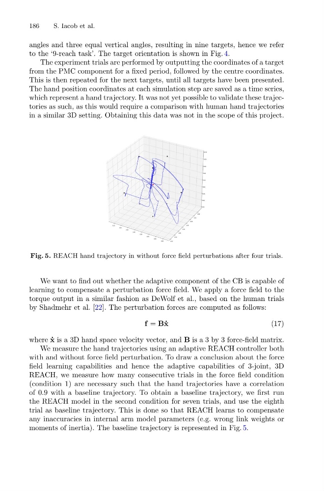
Fig. 5. REACH hand trajectory in without force field perturbations after four trials.
We want to find out whether the adaptive component of the CB is capable of
learning to compensate a perturbation force field. We apply a force field to the
torque output in a similar fashion as DeWolf et al., based on the human trials
by Shadmehr et al. [22]. The perturbation forces are computed as follows:
f = B ˙
x
(17)
where ˙
x is a 3D hand space velocity vector, and B is a 3 by 3 force-field matrix.
We measure the hand trajectories using an adaptive REACH controller both
with and without force field perturbation. To draw a conclusion about the force
field learning capabilities and hence the adaptive capabilities of 3-joint, 3D
REACH, we measure how many consecutive trials in the force field condition
(condition 1) are necessary such that the hand trajectories have a correlation
of 0.9 with a baseline trajectory. To obtain a baseline trajectory, we first run
the REACH model in the second condition for seven trials, and use the eighth
trial as baseline trajectory. This is done so that REACH learns to compensate
any inaccuracies in internal arm model parameters (e.g. wrong link weights or
moments of inertia). The baseline trajectory is represented in Fig. 5.
S. Iacob et al.
angles and three equal vertical angles, resulting in nine targets, hence we refer
to the ‘9-reach task’. The target orientation is shown in Fig. 4.
The experiment trials are performed by outputting the coordinates of a target
from the PMC component for a fixed period, followed by the centre coordinates.
This is then repeated for the next targets, until all targets have been presented.
The hand position coordinates at each simulation step are saved as a time series,
which represent a hand trajectory. It was not yet possible to validate these trajectories as such, as this would require a comparison with human hand trajectories
in a similar 3D setting. Obtaining this data was not in the scope of this project.
Fig. 5. REACH hand trajectory in without force field perturbations after four trials.
We want to find out whether the adaptive component of the CB is capable of
learning to compensate a perturbation force field. We apply a force field to the
torque output in a similar fashion as DeWolf et al., based on the human trials
by Shadmehr et al. [22]. The perturbation forces are computed as follows:
f = B ˙
x
(17)
where ˙
x is a 3D hand space velocity vector, and B is a 3 by 3 force-field matrix.
We measure the hand trajectories using an adaptive REACH controller both
with and without force field perturbation. To draw a conclusion about the force
field learning capabilities and hence the adaptive capabilities of 3-joint, 3D
REACH, we measure how many consecutive trials in the force field condition
(condition 1) are necessary such that the hand trajectories have a correlation
of 0.9 with a baseline trajectory. To obtain a baseline trajectory, we first run
the REACH model in the second condition for seven trials, and use the eighth
trial as baseline trajectory. This is done so that REACH learns to compensate
any inaccuracies in internal arm model parameters (e.g. wrong link weights or
moments of inertia). The baseline trajectory is represented in Fig. 5.