

Improving Recall in an Associative Neural Network Model of the Hippocampus
5
2 borrowed cells
from one pattern
to another
20% overlap
in 10 active cells
per pattern
Non pattern cell
Common cells between 1st and 2nd pattern
Common cells between 2nd and 3rd pattern
Common cells between 3rd and 4th pattern
Common cells between 4th and 5th pattern
Common cells between 5th and 1st pattern
1st
2nd
3rd
4th
5th
Number of
stored patterns
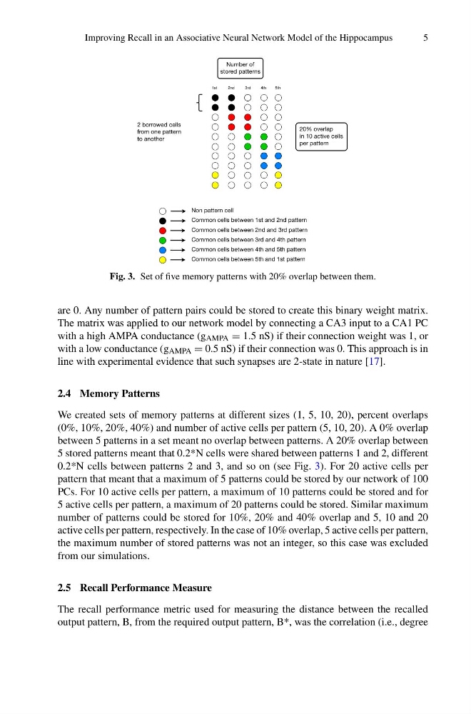
Fig. 3. Set of five memory patterns with 20% overlap between them.
are 0. Any number of pattern pairs could be stored to create this binary weight matrix.
The matrix was applied to our network model by connecting a CA3 input to a CA1 PC
with a high AMPA conductance (g AMPA = 1.5 nS) if their connection weight was 1, or
with a low conductance (g AMPA = 0.5 nS) if their connection was 0. This approach is in
line with experimental evidence that such synapses are 2-state in nature [17].
2.4 Memory Patterns
We created sets of memory patterns at different sizes (1, 5, 10, 20), percent overlaps
(0%, 10%, 20%, 40%) and number of active cells per pattern (5, 10, 20). A 0% overlap
between 5 patterns in a set meant no overlap between patterns. A 20% overlap between
5 stored patterns meant that 0.2*N cells were shared between patterns 1 and 2, different
0.2*N cells between patterns 2 and 3, and so on (see Fig. 3). For 20 active cells per
pattern that meant that a maximum of 5 patterns could be stored by our network of 100
PCs. For 10 active cells per pattern, a maximum of 10 patterns could be stored and for
5 active cells per pattern, a maximum of 20 patterns could be stored. Similar maximum
number of patterns could be stored for 10%, 20% and 40% overlap and 5, 10 and 20
active cells per pattern, respectively. In the case of 10% overlap, 5 active cells per pattern,
the maximum number of stored patterns was not an integer, so this case was excluded
from our simulations.
2.5 Recall Performance Measure
The recall performance metric used for measuring the distance between the recalled
output pattern, B, from the required output pattern, B*, was the correlation (i.e., degree
5
2 borrowed cells
from one pattern
to another
20% overlap
in 10 active cells
per pattern
Non pattern cell
Common cells between 1st and 2nd pattern
Common cells between 2nd and 3rd pattern
Common cells between 3rd and 4th pattern
Common cells between 4th and 5th pattern
Common cells between 5th and 1st pattern
1st
2nd
3rd
4th
5th
Number of
stored patterns
Fig. 3. Set of five memory patterns with 20% overlap between them.
are 0. Any number of pattern pairs could be stored to create this binary weight matrix.
The matrix was applied to our network model by connecting a CA3 input to a CA1 PC
with a high AMPA conductance (g AMPA = 1.5 nS) if their connection weight was 1, or
with a low conductance (g AMPA = 0.5 nS) if their connection was 0. This approach is in
line with experimental evidence that such synapses are 2-state in nature [17].
2.4 Memory Patterns
We created sets of memory patterns at different sizes (1, 5, 10, 20), percent overlaps
(0%, 10%, 20%, 40%) and number of active cells per pattern (5, 10, 20). A 0% overlap
between 5 patterns in a set meant no overlap between patterns. A 20% overlap between
5 stored patterns meant that 0.2*N cells were shared between patterns 1 and 2, different
0.2*N cells between patterns 2 and 3, and so on (see Fig. 3). For 20 active cells per
pattern that meant that a maximum of 5 patterns could be stored by our network of 100
PCs. For 10 active cells per pattern, a maximum of 10 patterns could be stored and for
5 active cells per pattern, a maximum of 20 patterns could be stored. Similar maximum
number of patterns could be stored for 10%, 20% and 40% overlap and 5, 10 and 20
active cells per pattern, respectively. In the case of 10% overlap, 5 active cells per pattern,
the maximum number of stored patterns was not an integer, so this case was excluded
from our simulations.
2.5 Recall Performance Measure
The recall performance metric used for measuring the distance between the recalled
output pattern, B, from the required output pattern, B*, was the correlation (i.e., degree