

112
M. N. Fitzpatrick et al.
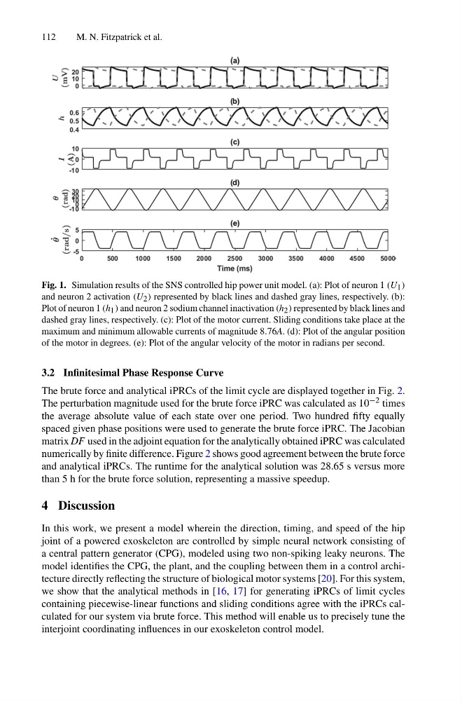
Fig. 1. Simulation results of the SNS controlled hip power unit model. (a): Plot of neuron 1 (U 1 )
and neuron 2 activation (U 2 ) represented by black lines and dashed gray lines, respectively. (b):
Plot of neuron 1 (h 1 ) and neuron 2 sodium channel inactivation (h 2 ) represented by black lines and
dashed gray lines, respectively. (c): Plot of the motor current. Sliding conditions take place at the
maximum and minimum allowable currents of magnitude 8.76A. (d): Plot of the angular position
of the motor in degrees. (e): Plot of the angular velocity of the motor in radians per second.
3.2 Infinitesimal Phase Response Curve
The brute force and analytical iPRCs of the limit cycle are displayed together in Fig. 2.
The perturbation magnitude used for the brute force iPRC was calculated as 10 −2 times
the average absolute value of each state over one period. Two hundred fifty equally
spaced given phase positions were used to generate the brute force iPRC. The Jacobian
matrix DF used in the adjoint equation for the analytically obtained iPRC was calculated
numerically by finite difference. Figure 2 shows good agreement between the brute force
and analytical iPRCs. The runtime for the analytical solution was 28.65 s versus more
than 5 h for the brute force solution, representing a massive speedup.
4 Discussion
In this work, we present a model wherein the direction, timing, and speed of the hip
joint of a powered exoskeleton are controlled by simple neural network consisting of
a central pattern generator (CPG), modeled using two non-spiking leaky neurons. The
model identifies the CPG, the plant, and the coupling between them in a control architecture directly reflecting the structure of biological motor systems [20]. For this system,
we show that the analytical methods in [16, 17] for generating iPRCs of limit cycles
containing piecewise-linear functions and sliding conditions agree with the iPRCs calculated for our system via brute force. This method will enable us to precisely tune the
interjoint coordinating influences in our exoskeleton control model.
M. N. Fitzpatrick et al.
Fig. 1. Simulation results of the SNS controlled hip power unit model. (a): Plot of neuron 1 (U 1 )
and neuron 2 activation (U 2 ) represented by black lines and dashed gray lines, respectively. (b):
Plot of neuron 1 (h 1 ) and neuron 2 sodium channel inactivation (h 2 ) represented by black lines and
dashed gray lines, respectively. (c): Plot of the motor current. Sliding conditions take place at the
maximum and minimum allowable currents of magnitude 8.76A. (d): Plot of the angular position
of the motor in degrees. (e): Plot of the angular velocity of the motor in radians per second.
3.2 Infinitesimal Phase Response Curve
The brute force and analytical iPRCs of the limit cycle are displayed together in Fig. 2.
The perturbation magnitude used for the brute force iPRC was calculated as 10 −2 times
the average absolute value of each state over one period. Two hundred fifty equally
spaced given phase positions were used to generate the brute force iPRC. The Jacobian
matrix DF used in the adjoint equation for the analytically obtained iPRC was calculated
numerically by finite difference. Figure 2 shows good agreement between the brute force
and analytical iPRCs. The runtime for the analytical solution was 28.65 s versus more
than 5 h for the brute force solution, representing a massive speedup.
4 Discussion
In this work, we present a model wherein the direction, timing, and speed of the hip
joint of a powered exoskeleton are controlled by simple neural network consisting of
a central pattern generator (CPG), modeled using two non-spiking leaky neurons. The
model identifies the CPG, the plant, and the coupling between them in a control architecture directly reflecting the structure of biological motor systems [20]. For this system,
we show that the analytical methods in [16, 17] for generating iPRCs of limit cycles
containing piecewise-linear functions and sliding conditions agree with the iPRCs calculated for our system via brute force. This method will enable us to precisely tune the
interjoint coordinating influences in our exoskeleton control model.