

110
M. N. Fitzpatrick et al.
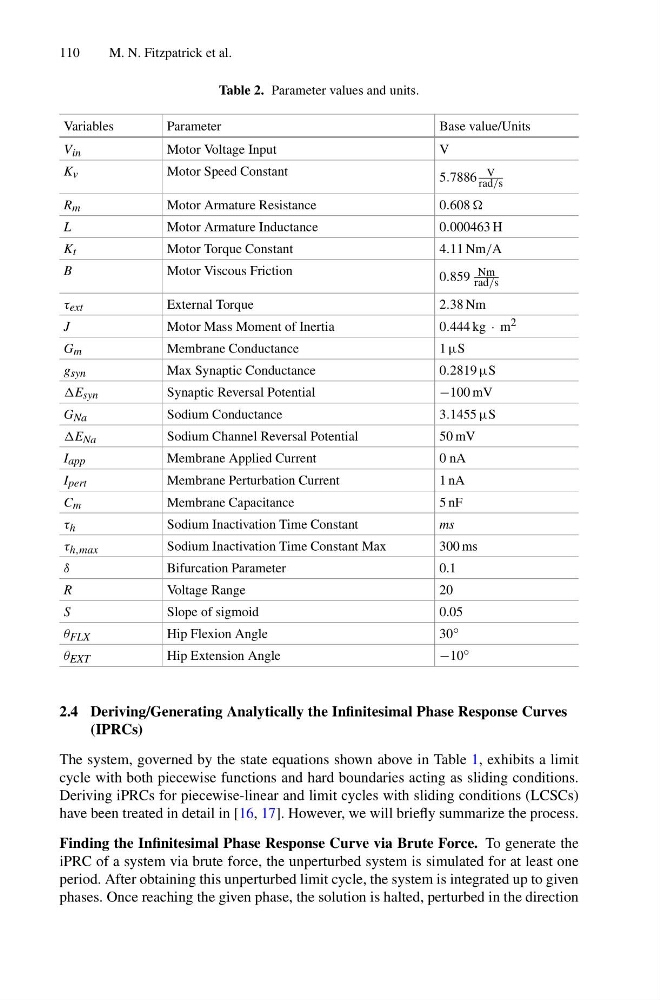
Table 2. Parameter values and units.
Variables
Parameter
Base value/Units
V in
Motor Voltage Input
V
K v
Motor Speed Constant
5.7886 V
rad/s
R m
Motor Armature Resistance
0.608
L
Motor Armature Inductance
0.000463 H
K t
Motor Torque Constant
4.11 Nm/A
B
Motor Viscous Friction
0.859 Nm
rad/s
τ ext
External Torque
2.38 Nm
J
Motor Mass Moment of Inertia
0.444 kg · m 2
G m
Membrane Conductance
1 µS
g syn
Max Synaptic Conductance
0.2819 µS
E syn
Synaptic Reversal Potential
−100 mV
G Na
Sodium Conductance
3.1455 µS
E Na
Sodium Channel Reversal Potential
50 mV
I app
Membrane Applied Current
0 nA
I pert
Membrane Perturbation Current
1 nA
C m
Membrane Capacitance
5 nF
τ h
Sodium Inactivation Time Constant
ms
τ h,max
Sodium Inactivation Time Constant Max
300 ms
δ
Bifurcation Parameter
0.1
R
Voltage Range
20
S
Slope of sigmoid
0.05
θ FLX
Hip Flexion Angle
30 ◦
θ EXT
Hip Extension Angle
−10 ◦
2.4 Deriving/Generating Analytically the Infinitesimal Phase Response Curves
(IPRCs)
The system, governed by the state equations shown above in Table 1, exhibits a limit
cycle with both piecewise functions and hard boundaries acting as sliding conditions.
Deriving iPRCs for piecewise-linear and limit cycles with sliding conditions (LCSCs)
have been treated in detail in [16, 17]. However, we will briefly summarize the process.
Finding the Infinitesimal Phase Response Curve via Brute Force. To generate the
iPRC of a system via brute force, the unperturbed system is simulated for at least one
period. After obtaining this unperturbed limit cycle, the system is integrated up to given
phases. Once reaching the given phase, the solution is halted, perturbed in the direction
M. N. Fitzpatrick et al.
Table 2. Parameter values and units.
Variables
Parameter
Base value/Units
V in
Motor Voltage Input
V
K v
Motor Speed Constant
5.7886 V
rad/s
R m
Motor Armature Resistance
0.608
L
Motor Armature Inductance
0.000463 H
K t
Motor Torque Constant
4.11 Nm/A
B
Motor Viscous Friction
0.859 Nm
rad/s
τ ext
External Torque
2.38 Nm
J
Motor Mass Moment of Inertia
0.444 kg · m 2
G m
Membrane Conductance
1 µS
g syn
Max Synaptic Conductance
0.2819 µS
E syn
Synaptic Reversal Potential
−100 mV
G Na
Sodium Conductance
3.1455 µS
E Na
Sodium Channel Reversal Potential
50 mV
I app
Membrane Applied Current
0 nA
I pert
Membrane Perturbation Current
1 nA
C m
Membrane Capacitance
5 nF
τ h
Sodium Inactivation Time Constant
ms
τ h,max
Sodium Inactivation Time Constant Max
300 ms
δ
Bifurcation Parameter
0.1
R
Voltage Range
20
S
Slope of sigmoid
0.05
θ FLX
Hip Flexion Angle
30 ◦
θ EXT
Hip Extension Angle
−10 ◦
2.4 Deriving/Generating Analytically the Infinitesimal Phase Response Curves
(IPRCs)
The system, governed by the state equations shown above in Table 1, exhibits a limit
cycle with both piecewise functions and hard boundaries acting as sliding conditions.
Deriving iPRCs for piecewise-linear and limit cycles with sliding conditions (LCSCs)
have been treated in detail in [16, 17]. However, we will briefly summarize the process.
Finding the Infinitesimal Phase Response Curve via Brute Force. To generate the
iPRC of a system via brute force, the unperturbed system is simulated for at least one
period. After obtaining this unperturbed limit cycle, the system is integrated up to given
phases. Once reaching the given phase, the solution is halted, perturbed in the direction