

Robotics Application of a Method for Analytically Computing Infinitesimal
107
2.2 Neural Dynamics
The neural dynamics contribute four state variables to the system. These variables model
the activation level of the two neurons in our CPG, as well as those neurons’ persistent
sodium channel inactivation.
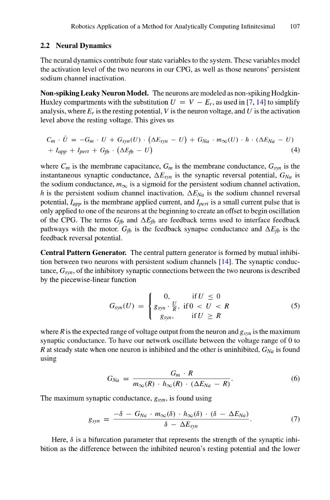
Non-spiking Leaky Neuron Model. The neurons are modeled as non-spiking HodgkinHuxley compartments with the substitution U = V − E r , as used in [7, 14] to simplify
analysis, where E r is the resting potential, V is the neuron voltage, and U is the activation
level above the resting voltage. This gives us
C m · ˙
U = −G m · U + G syn (U ) ·
E syn − U
+ G Na · m ∞ (U ) · h · (E Na − U )
+ I app + I pert + G fb ·
E fb − U
(4)
where C m is the membrane capacitance, G m is the membrane conductance, G syn is the
instantaneous synaptic conductance, E syn is the synaptic reversal potential, G Na is
the sodium conductance, m ∞ is a sigmoid for the persistent sodium channel activation,
h is the persistent sodium channel inactivation, E Na is the sodium channel reversal
potential, I app is the membrane applied current, and I pert is a small current pulse that is
only applied to one of the neurons at the beginning to create an offset to begin oscillation
of the CPG. The terms G fb and E fb are feedback terms used to interface feedback
pathways with the motor. G fb is the feedback synapse conductance and E fb is the
feedback reversal potential.
Central Pattern Generator. The central pattern generator is formed by mutual inhibition between two neurons with persistent sodium channels [14]. The synaptic conductance, G syn , of the inhibitory synaptic connections between the two neurons is described
by the piecewise-linear function
G syn (U ) =
⎧
⎨
⎩
0,
g syn ·
U
R ,
g syn ,
if U ≤ 0
if 0 < U < R
if U ≥ R
(5)
where R is the expected range of voltage output from the neuron and g syn is the maximum
synaptic conductance. To have our network oscillate between the voltage range of 0 to
R at steady state when one neuron is inhibited and the other is uninhibited, G Na is found
using
G Na =
G m · R
m ∞ (R) · h ∞ (R) · (E Na − R)
.
(6)
The maximum synaptic conductance, g syn , is found using
g syn =
−δ − G Na · m ∞ (δ) · h ∞ (δ) · (δ − E Na )
δ − E syn
.
(7)
Here, δ is a bifurcation parameter that represents the strength of the synaptic inhibition as the difference between the inhibited neuron’s resting potential and the lower
107
2.2 Neural Dynamics
The neural dynamics contribute four state variables to the system. These variables model
the activation level of the two neurons in our CPG, as well as those neurons’ persistent
sodium channel inactivation.
Non-spiking Leaky Neuron Model. The neurons are modeled as non-spiking HodgkinHuxley compartments with the substitution U = V − E r , as used in [7, 14] to simplify
analysis, where E r is the resting potential, V is the neuron voltage, and U is the activation
level above the resting voltage. This gives us
C m · ˙
U = −G m · U + G syn (U ) ·
E syn − U
+ G Na · m ∞ (U ) · h · (E Na − U )
+ I app + I pert + G fb ·
E fb − U
(4)
where C m is the membrane capacitance, G m is the membrane conductance, G syn is the
instantaneous synaptic conductance, E syn is the synaptic reversal potential, G Na is
the sodium conductance, m ∞ is a sigmoid for the persistent sodium channel activation,
h is the persistent sodium channel inactivation, E Na is the sodium channel reversal
potential, I app is the membrane applied current, and I pert is a small current pulse that is
only applied to one of the neurons at the beginning to create an offset to begin oscillation
of the CPG. The terms G fb and E fb are feedback terms used to interface feedback
pathways with the motor. G fb is the feedback synapse conductance and E fb is the
feedback reversal potential.
Central Pattern Generator. The central pattern generator is formed by mutual inhibition between two neurons with persistent sodium channels [14]. The synaptic conductance, G syn , of the inhibitory synaptic connections between the two neurons is described
by the piecewise-linear function
G syn (U ) =
⎧
⎨
⎩
0,
g syn ·
U
R ,
g syn ,
if U ≤ 0
if 0 < U < R
if U ≥ R
(5)
where R is the expected range of voltage output from the neuron and g syn is the maximum
synaptic conductance. To have our network oscillate between the voltage range of 0 to
R at steady state when one neuron is inhibited and the other is uninhibited, G Na is found
using
G Na =
G m · R
m ∞ (R) · h ∞ (R) · (E Na − R)
.
(6)
The maximum synaptic conductance, g syn , is found using
g syn =
−δ − G Na · m ∞ (δ) · h ∞ (δ) · (δ − E Na )
δ − E syn
.
(7)
Here, δ is a bifurcation parameter that represents the strength of the synaptic inhibition as the difference between the inhibited neuron’s resting potential and the lower