

106
M. N. Fitzpatrick et al.
2 Methods
This work establishes a system wherein the direction, timing, and speed of the hip joint
of a powered exoskeleton is controlled by simple neural network consisting of a central
pattern generator (CPG), modeled using two non-spiking leaky neurons. The hip joint is
powered by a DC motor with a gearbox, and the rotation of the joint provides feedback
to the CPG.
2.1 Motor Dynamics
The hip power unit is the actuator driving the movement. It is composed of a DC motor
paired with a transmission to produce a larger torque, while still being capable of outputting the needed speeds of the hip during walking locomotion. The power unit can be
modeled as a motor.
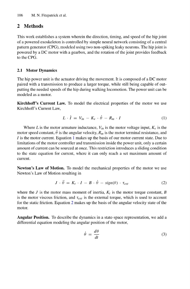
Kirchhoff’s Current Law. To model the electrical properties of the motor we use
Kirchhoff’s Current Law,
L · ˙
I = V in − K v · ˙
θ − R m · I
(1)
Where L is the motor armature inductance, V in is the motor voltage input, K v is the
motor speed constant, ˙
θ is the angular velocity, R m is the motor terminal resistance, and
I is the motor current. Equation 1 makes up the basis of our motor current state. Due to
limitations of the motor controller and transmission inside the power unit, only a certain
amount of current can be sourced at once. This restriction introduces a sliding condition
to the state equation for current, where it can only reach a set maximum amount of
current.
Newton’s Law of Motion. To model the mechanical properties of the motor we use
Newton’s Law of Motion resulting in
J · ¨
θ = K t · I − B · ˙
θ − sign(θ ) · τ ext
(2)
where the J is the motor mass moment of inertia, K t is the motor torque constant, B
is the motor viscous friction, and τ ext is the external torque, which is used to account
for the static friction. Equation 2 makes up the basis of the angular velocity state of the
motor.
Angular Position. To describe the dynamics in a state-space representation, we add a
differential equation modeling the angular position of the motor,
˙
θ =
d θ
dt
(3)
M. N. Fitzpatrick et al.
2 Methods
This work establishes a system wherein the direction, timing, and speed of the hip joint
of a powered exoskeleton is controlled by simple neural network consisting of a central
pattern generator (CPG), modeled using two non-spiking leaky neurons. The hip joint is
powered by a DC motor with a gearbox, and the rotation of the joint provides feedback
to the CPG.
2.1 Motor Dynamics
The hip power unit is the actuator driving the movement. It is composed of a DC motor
paired with a transmission to produce a larger torque, while still being capable of outputting the needed speeds of the hip during walking locomotion. The power unit can be
modeled as a motor.
Kirchhoff’s Current Law. To model the electrical properties of the motor we use
Kirchhoff’s Current Law,
L · ˙
I = V in − K v · ˙
θ − R m · I
(1)
Where L is the motor armature inductance, V in is the motor voltage input, K v is the
motor speed constant, ˙
θ is the angular velocity, R m is the motor terminal resistance, and
I is the motor current. Equation 1 makes up the basis of our motor current state. Due to
limitations of the motor controller and transmission inside the power unit, only a certain
amount of current can be sourced at once. This restriction introduces a sliding condition
to the state equation for current, where it can only reach a set maximum amount of
current.
Newton’s Law of Motion. To model the mechanical properties of the motor we use
Newton’s Law of Motion resulting in
J · ¨
θ = K t · I − B · ˙
θ − sign(θ ) · τ ext
(2)
where the J is the motor mass moment of inertia, K t is the motor torque constant, B
is the motor viscous friction, and τ ext is the external torque, which is used to account
for the static friction. Equation 2 makes up the basis of the angular velocity state of the
motor.
Angular Position. To describe the dynamics in a state-space representation, we add a
differential equation modeling the angular position of the motor,
˙
θ =
d θ
dt
(3)