

17 Microsphere-Assisted Interference Microscopy
451
17.2 Microsphere-Assisted Microscopy for 2D Imaging
17.2.1 Principle
The approach of microsphere-assisted microscopy for 2D imaging consists of simply
placing a transparent microsphere between the sample to be tested and an optical
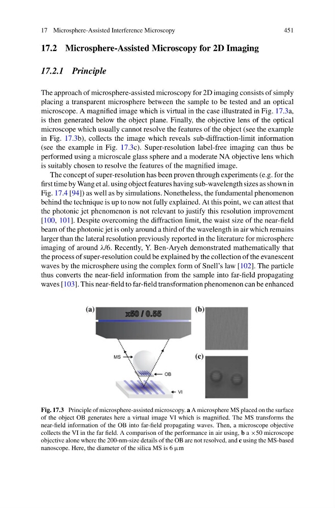
microscope. A magnified image which is virtual in the case illustrated in Fig. 17.3a,
is then generated below the object plane. Finally, the objective lens of the optical
microscope which usually cannot resolve the features of the object (see the example
in Fig. 17.3b), collects the image which reveals sub-diffraction-limit information
(see the example in Fig. 17.3c). Super-resolution label-free imaging can thus be
performed using a microscale glass sphere and a moderate NA objective lens which
is suitably chosen to resolve the features of the magnified image.
The concept of super-resolution has been proven through experiments (e.g. for the
first time by Wang et al. using object features having sub-wavelength sizes as shown in
Fig. 17.4 [94]) as well as by simulations. Nonetheless, the fundamental phenomenon
behind the technique is up to now not fully explained. At this point, we can attest that
the photonic jet phenomenon is not relevant to justify this resolution improvement
[100, 101]. Despite overcoming the diffraction limit, the waist size of the near-field
beam of the photonic jet is only around a third of the wavelength in air which remains
larger than the lateral resolution previously reported in the literature for microsphere
imaging of around λ/6. Recently, Y. Ben-Aryeh demonstrated mathematically that
the process of super-resolution could be explained by the collection of the evanescent
waves by the microsphere using the complex form of Snell’s law [102]. The particle
thus converts the near-field information from the sample into far-field propagating
waves [103]. This near-field to far-field transformation phenomenon can be enhanced
Fig. 17.3 Principle of microsphere-assisted microscopy. a A microsphere MS placed on the surface
of the object OB generates here a virtual image VI which is magnified. The MS transforms the
near-field information of the OB into far-field propagating waves. Then, a microscope objective
collects the VI in the far field. A comparison of the performance in air using, b a ×50 microscope
objective alone where the 200-nm-size details of the OB are not resolved, and c using the MS-based
nanoscope. Here, the diameter of the silica MS is 6 µm
451
17.2 Microsphere-Assisted Microscopy for 2D Imaging
17.2.1 Principle
The approach of microsphere-assisted microscopy for 2D imaging consists of simply
placing a transparent microsphere between the sample to be tested and an optical
microscope. A magnified image which is virtual in the case illustrated in Fig. 17.3a,
is then generated below the object plane. Finally, the objective lens of the optical
microscope which usually cannot resolve the features of the object (see the example
in Fig. 17.3b), collects the image which reveals sub-diffraction-limit information
(see the example in Fig. 17.3c). Super-resolution label-free imaging can thus be
performed using a microscale glass sphere and a moderate NA objective lens which
is suitably chosen to resolve the features of the magnified image.
The concept of super-resolution has been proven through experiments (e.g. for the
first time by Wang et al. using object features having sub-wavelength sizes as shown in
Fig. 17.4 [94]) as well as by simulations. Nonetheless, the fundamental phenomenon
behind the technique is up to now not fully explained. At this point, we can attest that
the photonic jet phenomenon is not relevant to justify this resolution improvement
[100, 101]. Despite overcoming the diffraction limit, the waist size of the near-field
beam of the photonic jet is only around a third of the wavelength in air which remains
larger than the lateral resolution previously reported in the literature for microsphere
imaging of around λ/6. Recently, Y. Ben-Aryeh demonstrated mathematically that
the process of super-resolution could be explained by the collection of the evanescent
waves by the microsphere using the complex form of Snell’s law [102]. The particle
thus converts the near-field information from the sample into far-field propagating
waves [103]. This near-field to far-field transformation phenomenon can be enhanced
Fig. 17.3 Principle of microsphere-assisted microscopy. a A microsphere MS placed on the surface
of the object OB generates here a virtual image VI which is magnified. The MS transforms the
near-field information of the OB into far-field propagating waves. Then, a microscope objective
collects the VI in the far field. A comparison of the performance in air using, b a ×50 microscope
objective alone where the 200-nm-size details of the OB are not resolved, and c using the MS-based
nanoscope. Here, the diameter of the silica MS is 6 µm