

16 Theoretical Foundations of Super-Resolution in Microspherical Nanoscopy
429
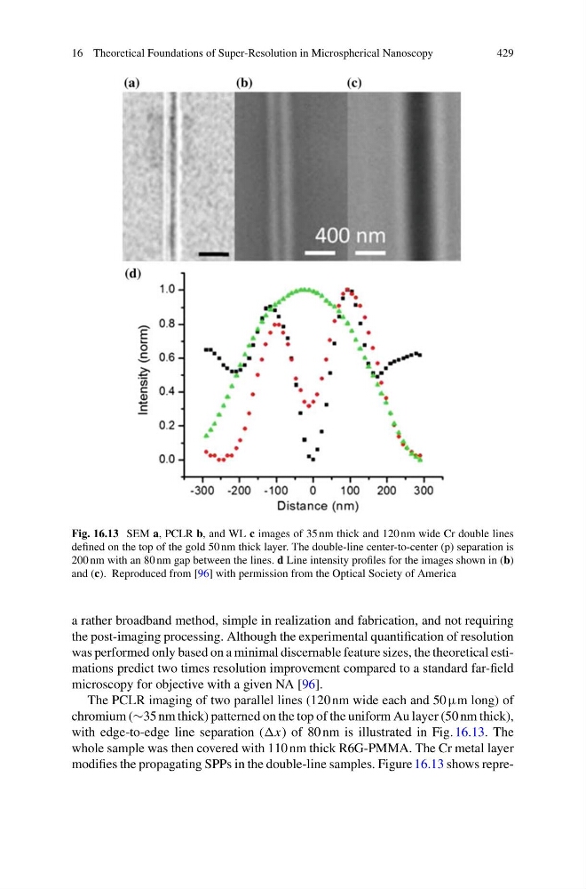
Fig. 16.13 SEM a, PCLR b, and WL c images of 35 nm thick and 120 nm wide Cr double lines
defined on the top of the gold 50 nm thick layer. The double-line center-to-center (p) separation is
200 nm with an 80 nm gap between the lines. d Line intensity profiles for the images shown in (b)
and (c). Reproduced from [96] with permission from the Optical Society of America
a rather broadband method, simple in realization and fabrication, and not requiring
the post-imaging processing. Although the experimental quantification of resolution
was performed only based on a minimal discernable feature sizes, the theoretical estimations predict two times resolution improvement compared to a standard far-field
microscopy for objective with a given NA [96].
The PCLR imaging of two parallel lines (120 nm wide each and 50 µm long) of
chromium (∼35 nm thick) patterned on the top of the uniform Au layer (50 nm thick),
with edge-to-edge line separation (x) of 80 nm is illustrated in Fig. 16.13. The
whole sample was then covered with 110 nm thick R6G-PMMA. The Cr metal layer
modifies the propagating SPPs in the double-line samples. Figure 16.13 shows repre-
429
Fig. 16.13 SEM a, PCLR b, and WL c images of 35 nm thick and 120 nm wide Cr double lines
defined on the top of the gold 50 nm thick layer. The double-line center-to-center (p) separation is
200 nm with an 80 nm gap between the lines. d Line intensity profiles for the images shown in (b)
and (c). Reproduced from [96] with permission from the Optical Society of America
a rather broadband method, simple in realization and fabrication, and not requiring
the post-imaging processing. Although the experimental quantification of resolution
was performed only based on a minimal discernable feature sizes, the theoretical estimations predict two times resolution improvement compared to a standard far-field
microscopy for objective with a given NA [96].
The PCLR imaging of two parallel lines (120 nm wide each and 50 µm long) of
chromium (∼35 nm thick) patterned on the top of the uniform Au layer (50 nm thick),
with edge-to-edge line separation (x) of 80 nm is illustrated in Fig. 16.13. The
whole sample was then covered with 110 nm thick R6G-PMMA. The Cr metal layer
modifies the propagating SPPs in the double-line samples. Figure 16.13 shows repre-