

414
A. V. Maslov and V. N. Astratov
-4
-2
0
2
4
6
8
10
-2 -1 0 1 2
A
B
C
D
M
x/R
y/R
n b
j 0
(a)
(b)
Lens
Detector
d
R y
x
z
ϕ
(c)
n s
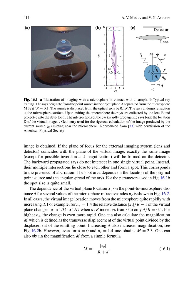
Fig. 16.1 a Illustration of imaging with a microsphere in contact with a sample. b Typical ray
tracing. The rays originate from the point source in the object plane A separated from the microsphere
M by d/R = 0.1. The source is displaced from the optical axis by 0.1R. The rays undergo refraction
at the microsphere surface. Upon exiting the microsphere the rays are collected by the lens B and
projected into the detector C. The intersections of the backwardly propagating rays form the location
D of the virtual image. c Geometry used for the rigorous calculation of the image produced by the
current source j 0 emitting near the microsphere. Reproduced from [53] with permission of the
American Physical Society
image is obtained. If the plane of focus for the external imaging system (lens and
detector) coincides with the plane of the virtual image, exactly the same image
(except for possible inversion and magnification) will be formed on the detector.
The backward propagated rays do not intersect in one single virtual point. Instead,
their multiple intersections lie close to each other and form a spot. This corresponds
to the presence of aberration. The spot area depends on the location of the original
point source and the angular spread of the rays. For the parameters used in Fig. 16.1b
the spot size is quite small.
The dependence of the virtual plane location x v on the point-to-microsphere distance d for several values of the microsphere refractive index n s is shown in Fig. 16.2.
In all cases, the virtual image location moves from the microsphere quite rapidly with
increasing d. For example, for n s = 1.4 the relative distance |x v |/R − 1 of the virtual
plane changes from 1.34 to 1.97 when d/R increases from 0 to only d/R = 0.1. For
higher n s , the change is even more rapid. One can also calculate the magnification
M which is defined as the transverse displacement of the virtual point divided by the
displacement of the emitting point. Increasing d also increases magnification, see
Fig. 16.2b. However, even for d = 0 and n s = 1.4 one obtains M = 2.3. One can
also obtain the magnification M from a simple formula
M = −
|x v |
R + d
,
(16.1)
A. V. Maslov and V. N. Astratov
-4
-2
0
2
4
6
8
10
-2 -1 0 1 2
A
B
C
D
M
x/R
y/R
n b
j 0
(a)
(b)
Lens
Detector
d
R y
x
z
ϕ
(c)
n s
Fig. 16.1 a Illustration of imaging with a microsphere in contact with a sample. b Typical ray
tracing. The rays originate from the point source in the object plane A separated from the microsphere
M by d/R = 0.1. The source is displaced from the optical axis by 0.1R. The rays undergo refraction
at the microsphere surface. Upon exiting the microsphere the rays are collected by the lens B and
projected into the detector C. The intersections of the backwardly propagating rays form the location
D of the virtual image. c Geometry used for the rigorous calculation of the image produced by the
current source j 0 emitting near the microsphere. Reproduced from [53] with permission of the
American Physical Society
image is obtained. If the plane of focus for the external imaging system (lens and
detector) coincides with the plane of the virtual image, exactly the same image
(except for possible inversion and magnification) will be formed on the detector.
The backward propagated rays do not intersect in one single virtual point. Instead,
their multiple intersections lie close to each other and form a spot. This corresponds
to the presence of aberration. The spot area depends on the location of the original
point source and the angular spread of the rays. For the parameters used in Fig. 16.1b
the spot size is quite small.
The dependence of the virtual plane location x v on the point-to-microsphere distance d for several values of the microsphere refractive index n s is shown in Fig. 16.2.
In all cases, the virtual image location moves from the microsphere quite rapidly with
increasing d. For example, for n s = 1.4 the relative distance |x v |/R − 1 of the virtual
plane changes from 1.34 to 1.97 when d/R increases from 0 to only d/R = 0.1. For
higher n s , the change is even more rapid. One can also calculate the magnification
M which is defined as the transverse displacement of the virtual point divided by the
displacement of the emitting point. Increasing d also increases magnification, see
Fig. 16.2b. However, even for d = 0 and n s = 1.4 one obtains M = 2.3. One can
also obtain the magnification M from a simple formula
M = −
|x v |
R + d
,
(16.1)