

14 Label-Free Super-Resolution Imaging with Hyperbolic Materials
357
(a)
(b)
(c)
(d)
(e)
(f)
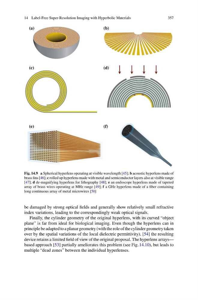
Fig. 14.9 a Spherical hyperlens operating at visible wavelength [45]; b acoustic hyperlens made of
brass fins [46]; c rolled up hyperlens made with metal and semiconductor layers also at visible range
[47]; d de-magnifying hyperlens for lithography [48]; e an endoscope hyperlens made of tapered
array of brass wires operating at MHz range [49]; f a GHz hyperlens made of a fiber containing
long continuous array of metal microwires [50]
be damaged by strong optical fields and generally show relatively small refractive
index variations, leading to the correspondingly weak optical signals.
Finally, the cylinder geometry of the original hyperlens, with its curved “object
plane” is far from ideal for biological imaging. Even though the hyperlens can in
principle be adapted to a planar geometry (with the role of the cylinder geometry taken
over by the spatial variations of the local dielectric permittivity), [54] the resulting
device retains a limited field of view of the original proposal. The hyperlens arrays—
based approach [53] partially ameliorates this problem (see Fig. 14.10), but leads to
multiple “dead zones” between the individual hyperlenses.
357
(a)
(b)
(c)
(d)
(e)
(f)
Fig. 14.9 a Spherical hyperlens operating at visible wavelength [45]; b acoustic hyperlens made of
brass fins [46]; c rolled up hyperlens made with metal and semiconductor layers also at visible range
[47]; d de-magnifying hyperlens for lithography [48]; e an endoscope hyperlens made of tapered
array of brass wires operating at MHz range [49]; f a GHz hyperlens made of a fiber containing
long continuous array of metal microwires [50]
be damaged by strong optical fields and generally show relatively small refractive
index variations, leading to the correspondingly weak optical signals.
Finally, the cylinder geometry of the original hyperlens, with its curved “object
plane” is far from ideal for biological imaging. Even though the hyperlens can in
principle be adapted to a planar geometry (with the role of the cylinder geometry taken
over by the spatial variations of the local dielectric permittivity), [54] the resulting
device retains a limited field of view of the original proposal. The hyperlens arrays—
based approach [53] partially ameliorates this problem (see Fig. 14.10), but leads to
multiple “dead zones” between the individual hyperlenses.