

14 Label-Free Super-Resolution Imaging with Hyperbolic Materials
355
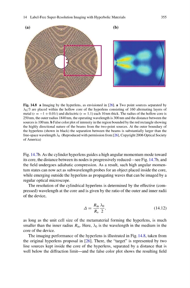
Fig. 14.8 a Imaging by the hyperlens, as envisioned in [26]. a Two point sources separated by
λ 0 /3 are placed within the hollow core of the hyperlens consisting of 160 alternating layers of
metal ( = −1 + 0.01i) and dielectric ( = 1.1) each 10 nm thick. The radius of the hollow core is
250 nm, the outer radius 1840 nm, the operating wavelength is 300 nm and the distance between the
sources is 100 nm. b False color plot of intensity in the region bounded by the red rectangle showing
the highly directional nature of the beams from the two-point sources. At the outer boundary of
the hyperlens (shown in black) the separation between the beams is substantially larger than the
free-space wavelength λ 0 (Reproduced with permission from [26], Copyright 2006 Optical Society
of America)
Fig. 14.7b. As the cylinder hyperlens guides a high angular momentum mode toward
its core, the distance between its nodes is progressively reduced—see Fig. 14.7b, and
the field undergoes adiabatic compression. As a result, such high angular momentum states can now act as subwavelength probes for an object placed inside the core,
while emerging outside the hyperlens as propagating waves that can be imaged by a
regular optical microscope.
The resolution of the cylindrical hyperlens is determined by the effective (compressed) wavelength at the core and is given by the ratio of the outer and inner radii
of the device,
Δ =
R in
R o
λ 0
2
,
(14.12)
as long as the unit cell size of the metamaterial forming the hyperlens, is much
smaller than the inner radius R in . Here, λ 0 is the wavelength in the medium in the
core of the device.
The imaging performance of the hyperlens is illustrated in Fig. 14.8, taken from
the original hyperlens proposal in [26]. There, the “target” is represented by two
line sources kept inside the core of the hyperlens, separated by a distance that is
well below the diffraction limit—and the false color plot shows the resulting field
355
Fig. 14.8 a Imaging by the hyperlens, as envisioned in [26]. a Two point sources separated by
λ 0 /3 are placed within the hollow core of the hyperlens consisting of 160 alternating layers of
metal ( = −1 + 0.01i) and dielectric ( = 1.1) each 10 nm thick. The radius of the hollow core is
250 nm, the outer radius 1840 nm, the operating wavelength is 300 nm and the distance between the
sources is 100 nm. b False color plot of intensity in the region bounded by the red rectangle showing
the highly directional nature of the beams from the two-point sources. At the outer boundary of
the hyperlens (shown in black) the separation between the beams is substantially larger than the
free-space wavelength λ 0 (Reproduced with permission from [26], Copyright 2006 Optical Society
of America)
Fig. 14.7b. As the cylinder hyperlens guides a high angular momentum mode toward
its core, the distance between its nodes is progressively reduced—see Fig. 14.7b, and
the field undergoes adiabatic compression. As a result, such high angular momentum states can now act as subwavelength probes for an object placed inside the core,
while emerging outside the hyperlens as propagating waves that can be imaged by a
regular optical microscope.
The resolution of the cylindrical hyperlens is determined by the effective (compressed) wavelength at the core and is given by the ratio of the outer and inner radii
of the device,
Δ =
R in
R o
λ 0
2
,
(14.12)
as long as the unit cell size of the metamaterial forming the hyperlens, is much
smaller than the inner radius R in . Here, λ 0 is the wavelength in the medium in the
core of the device.
The imaging performance of the hyperlens is illustrated in Fig. 14.8, taken from
the original hyperlens proposal in [26]. There, the “target” is represented by two
line sources kept inside the core of the hyperlens, separated by a distance that is
well below the diffraction limit—and the false color plot shows the resulting field