

13 Super-Resolution Microscopy Techniques Based …
335
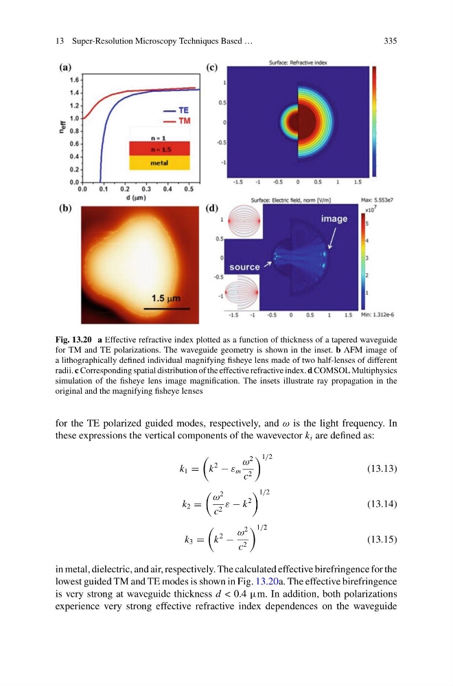
Fig. 13.20 a Effective refractive index plotted as a function of thickness of a tapered waveguide
for TM and TE polarizations. The waveguide geometry is shown in the inset. b AFM image of
a lithographically defined individual magnifying fisheye lens made of two half-lenses of different
radii. c Corresponding spatial distribution of the effective refractive index. d COMSOL Multiphysics
simulation of the fisheye lens image magnification. The insets illustrate ray propagation in the
original and the magnifying fisheye lenses
for the TE polarized guided modes, respectively, and ω is the light frequency. In
these expressions the vertical components of the wavevector k i are defined as:
k 1 =
k
2
− ε m
ω
2
c 2
1/2
(13.13)
k 2 =
ω
2
c 2 ε − k
2
1/2
(13.14)
k 3 =
k
2
−
ω
2
c 2
1/2
(13.15)
in metal, dielectric, and air, respectively. The calculated effective birefringence for the
lowest guided TM and TE modes is shown in Fig. 13.20a. The effective birefringence
is very strong at waveguide thickness d < 0.4 µm. In addition, both polarizations
experience very strong effective refractive index dependences on the waveguide
335
Fig. 13.20 a Effective refractive index plotted as a function of thickness of a tapered waveguide
for TM and TE polarizations. The waveguide geometry is shown in the inset. b AFM image of
a lithographically defined individual magnifying fisheye lens made of two half-lenses of different
radii. c Corresponding spatial distribution of the effective refractive index. d COMSOL Multiphysics
simulation of the fisheye lens image magnification. The insets illustrate ray propagation in the
original and the magnifying fisheye lenses
for the TE polarized guided modes, respectively, and ω is the light frequency. In
these expressions the vertical components of the wavevector k i are defined as:
k 1 =
k
2
− ε m
ω
2
c 2
1/2
(13.13)
k 2 =
ω
2
c 2 ε − k
2
1/2
(13.14)
k 3 =
k
2
−
ω
2
c 2
1/2
(13.15)
in metal, dielectric, and air, respectively. The calculated effective birefringence for the
lowest guided TM and TE modes is shown in Fig. 13.20a. The effective birefringence
is very strong at waveguide thickness d < 0.4 µm. In addition, both polarizations
experience very strong effective refractive index dependences on the waveguide