

13 Super-Resolution Microscopy Techniques Based …
327
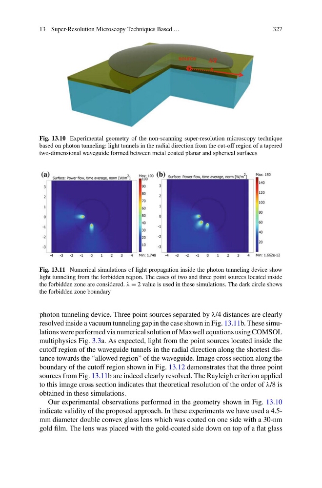
Fig. 13.10 Experimental geometry of the non-scanning super-resolution microscopy technique
based on photon tunneling: light tunnels in the radial direction from the cut-off region of a tapered
two-dimensional waveguide formed between metal coated planar and spherical surfaces
Fig. 13.11 Numerical simulations of light propagation inside the photon tunneling device show
light tunneling from the forbidden region. The cases of two and three point sources located inside
the forbidden zone are considered. λ = 2 value is used in these simulations. The dark circle shows
the forbidden zone boundary
photon tunneling device. Three point sources separated by λ/4 distances are clearly
resolved inside a vacuum tunneling gap in the case shown in Fig. 13.11b. These simulations were performed via numerical solution of Maxwell equations using COMSOL
multiphysics Fig. 3.3a. As expected, light from the point sources located inside the
cutoff region of the waveguide tunnels in the radial direction along the shortest distance towards the “allowed region” of the waveguide. Image cross section along the
boundary of the cutoff region shown in Fig. 13.12 demonstrates that the three point
sources from Fig. 13.11b are indeed clearly resolved. The Rayleigh criterion applied
to this image cross section indicates that theoretical resolution of the order of λ/8 is
obtained in these simulations.
Our experimental observations performed in the geometry shown in Fig. 13.10
indicate validity of the proposed approach. In these experiments we have used a 4.5mm diameter double convex glass lens which was coated on one side with a 30-nm
gold film. The lens was placed with the gold-coated side down on top of a flat glass
327
Fig. 13.10 Experimental geometry of the non-scanning super-resolution microscopy technique
based on photon tunneling: light tunnels in the radial direction from the cut-off region of a tapered
two-dimensional waveguide formed between metal coated planar and spherical surfaces
Fig. 13.11 Numerical simulations of light propagation inside the photon tunneling device show
light tunneling from the forbidden region. The cases of two and three point sources located inside
the forbidden zone are considered. λ = 2 value is used in these simulations. The dark circle shows
the forbidden zone boundary
photon tunneling device. Three point sources separated by λ/4 distances are clearly
resolved inside a vacuum tunneling gap in the case shown in Fig. 13.11b. These simulations were performed via numerical solution of Maxwell equations using COMSOL
multiphysics Fig. 3.3a. As expected, light from the point sources located inside the
cutoff region of the waveguide tunnels in the radial direction along the shortest distance towards the “allowed region” of the waveguide. Image cross section along the
boundary of the cutoff region shown in Fig. 13.12 demonstrates that the three point
sources from Fig. 13.11b are indeed clearly resolved. The Rayleigh criterion applied
to this image cross section indicates that theoretical resolution of the order of λ/8 is
obtained in these simulations.
Our experimental observations performed in the geometry shown in Fig. 13.10
indicate validity of the proposed approach. In these experiments we have used a 4.5mm diameter double convex glass lens which was coated on one side with a 30-nm
gold film. The lens was placed with the gold-coated side down on top of a flat glass