

128
N. Rahbany et al.
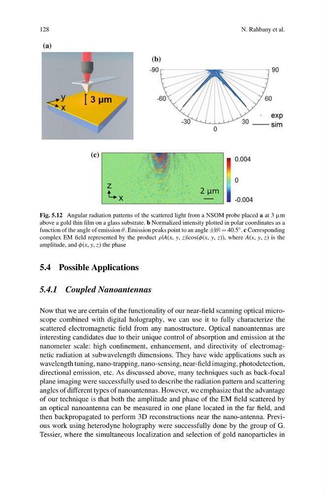
Fig. 5.12 Angular radiation patterns of the scattered light from a NSOM probe placed a at 3 μm
above a gold thin film on a glass substrate. b Normalized intensity plotted in polar coordinates as a
function of the angle of emission θ. Emission peaks point to an angle ±|θ| = 40.5°. c Corresponding
complex EM field represented by the product ρ|A(x, y, z)|cos(φ(x, y, z)), where A(x, y, z) is the
amplitude, and φ(x, y, z) the phase
5.4 Possible Applications
5.4.1 Coupled Nanoantennas
Now that we are certain of the functionality of our near-field scanning optical microscope combined with digital holography, we can use it to fully characterize the
scattered electromagnetic field from any nanostructure. Optical nanoantennas are
interesting candidates due to their unique control of absorption and emission at the
nanometer scale: high confinement, enhancement, and directivity of electromagnetic radiation at subwavelength dimensions. They have wide applications such as
wavelength tuning, nano-trapping, nano-sensing, near-field imaging, photodetection,
directional emission, etc. As discussed above, many techniques such as back-focal
plane imaging were successfully used to describe the radiation pattern and scattering
angles of different types of nanoantennas. However, we emphasize that the advantage
of our technique is that both the amplitude and phase of the EM field scattered by
an optical nanoantenna can be measured in one plane located in the far field, and
then backpropagated to perform 3D reconstructions near the nano-antenna. Previous work using heterodyne holography were successfully done by the group of G.
Tessier, where the simultaneous localization and selection of gold nanoparticles in
N. Rahbany et al.
Fig. 5.12 Angular radiation patterns of the scattered light from a NSOM probe placed a at 3 μm
above a gold thin film on a glass substrate. b Normalized intensity plotted in polar coordinates as a
function of the angle of emission θ. Emission peaks point to an angle ±|θ| = 40.5°. c Corresponding
complex EM field represented by the product ρ|A(x, y, z)|cos(φ(x, y, z)), where A(x, y, z) is the
amplitude, and φ(x, y, z) the phase
5.4 Possible Applications
5.4.1 Coupled Nanoantennas
Now that we are certain of the functionality of our near-field scanning optical microscope combined with digital holography, we can use it to fully characterize the
scattered electromagnetic field from any nanostructure. Optical nanoantennas are
interesting candidates due to their unique control of absorption and emission at the
nanometer scale: high confinement, enhancement, and directivity of electromagnetic radiation at subwavelength dimensions. They have wide applications such as
wavelength tuning, nano-trapping, nano-sensing, near-field imaging, photodetection,
directional emission, etc. As discussed above, many techniques such as back-focal
plane imaging were successfully used to describe the radiation pattern and scattering
angles of different types of nanoantennas. However, we emphasize that the advantage
of our technique is that both the amplitude and phase of the EM field scattered by
an optical nanoantenna can be measured in one plane located in the far field, and
then backpropagated to perform 3D reconstructions near the nano-antenna. Previous work using heterodyne holography were successfully done by the group of G.
Tessier, where the simultaneous localization and selection of gold nanoparticles in