

4 Tomographic Diffractive Microscopy …
95
the z-axis. A continuous wavelength scanning could provide an extended and filled
frequency support (Fig. 4.6b).
The main advantage of this wavelength variation approach is that a no-movingpart setup could be built, contrary to TDM with illumination rotation (or with sample
rotation, see next section). The drawback of this approach is that it gives access to
a more limited frequency support, compared to the previous one. The support being
asymmetric, the same restrictions as before will apply with respect to the sample
reconstruction, if a simple and direct Fourier inversion is used. A further possible
limitation is also that wide spectrum (“white”) coherent light sources are still of
limited availability, and complex. This explains that this approach, with standard
holographic microscopy, has not gain much success (variants in reflection microholography have been developed [108–110]).
An elegant solution to this problem has been proposed with the introduction
of white-light diffraction tomography [111–113], which can be considered as an
extension of phase contrast microscopy, but with a controllable phase mask, instead
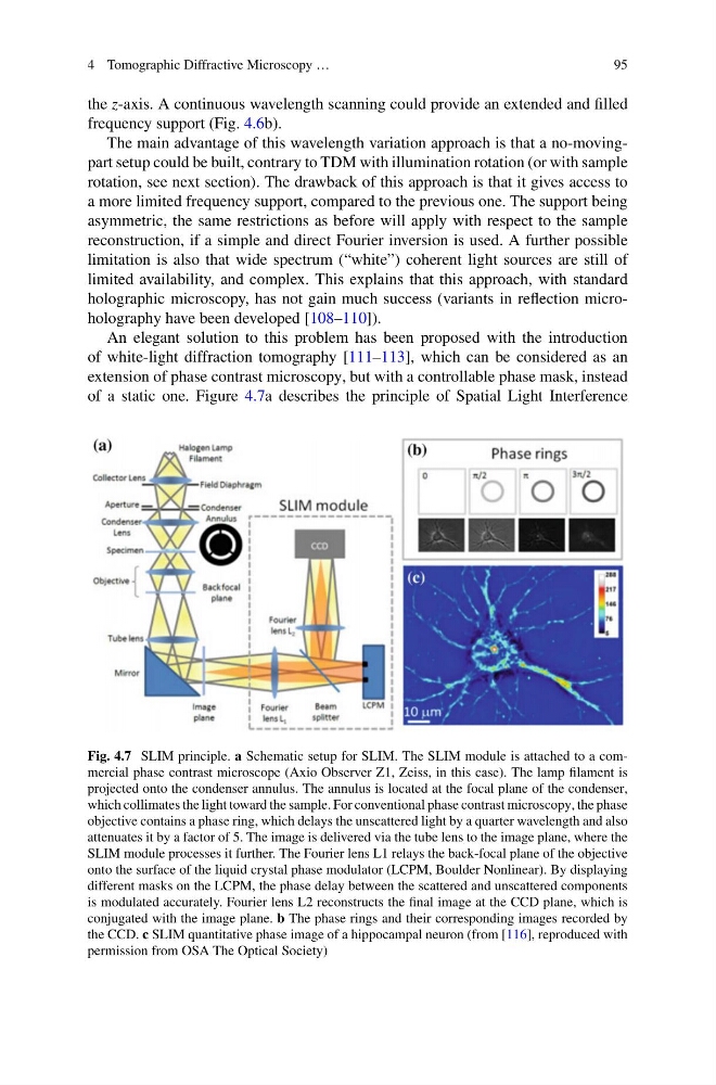
of a static one. Figure 4.7a describes the principle of Spatial Light Interference
Fig. 4.7 SLIM principle. a Schematic setup for SLIM. The SLIM module is attached to a commercial phase contrast microscope (Axio Observer Z1, Zeiss, in this case). The lamp filament is
projected onto the condenser annulus. The annulus is located at the focal plane of the condenser,
which collimates the light toward the sample. For conventional phase contrast microscopy, the phase
objective contains a phase ring, which delays the unscattered light by a quarter wavelength and also
attenuates it by a factor of 5. The image is delivered via the tube lens to the image plane, where the
SLIM module processes it further. The Fourier lens L1 relays the back-focal plane of the objective
onto the surface of the liquid crystal phase modulator (LCPM, Boulder Nonlinear). By displaying
different masks on the LCPM, the phase delay between the scattered and unscattered components
is modulated accurately. Fourier lens L2 reconstructs the final image at the CCD plane, which is
conjugated with the image plane. b The phase rings and their corresponding images recorded by
the CCD. c SLIM quantitative phase image of a hippocampal neuron (from [116], reproduced with
permission from OSA The Optical Society)
95
the z-axis. A continuous wavelength scanning could provide an extended and filled
frequency support (Fig. 4.6b).
The main advantage of this wavelength variation approach is that a no-movingpart setup could be built, contrary to TDM with illumination rotation (or with sample
rotation, see next section). The drawback of this approach is that it gives access to
a more limited frequency support, compared to the previous one. The support being
asymmetric, the same restrictions as before will apply with respect to the sample
reconstruction, if a simple and direct Fourier inversion is used. A further possible
limitation is also that wide spectrum (“white”) coherent light sources are still of
limited availability, and complex. This explains that this approach, with standard
holographic microscopy, has not gain much success (variants in reflection microholography have been developed [108–110]).
An elegant solution to this problem has been proposed with the introduction
of white-light diffraction tomography [111–113], which can be considered as an
extension of phase contrast microscopy, but with a controllable phase mask, instead
of a static one. Figure 4.7a describes the principle of Spatial Light Interference
Fig. 4.7 SLIM principle. a Schematic setup for SLIM. The SLIM module is attached to a commercial phase contrast microscope (Axio Observer Z1, Zeiss, in this case). The lamp filament is
projected onto the condenser annulus. The annulus is located at the focal plane of the condenser,
which collimates the light toward the sample. For conventional phase contrast microscopy, the phase
objective contains a phase ring, which delays the unscattered light by a quarter wavelength and also
attenuates it by a factor of 5. The image is delivered via the tube lens to the image plane, where the
SLIM module processes it further. The Fourier lens L1 relays the back-focal plane of the objective
onto the surface of the liquid crystal phase modulator (LCPM, Boulder Nonlinear). By displaying
different masks on the LCPM, the phase delay between the scattered and unscattered components
is modulated accurately. Fourier lens L2 reconstructs the final image at the CCD plane, which is
conjugated with the image plane. b The phase rings and their corresponding images recorded by
the CCD. c SLIM quantitative phase image of a hippocampal neuron (from [116], reproduced with
permission from OSA The Optical Society)