

330
H. Courtecuisse et al.
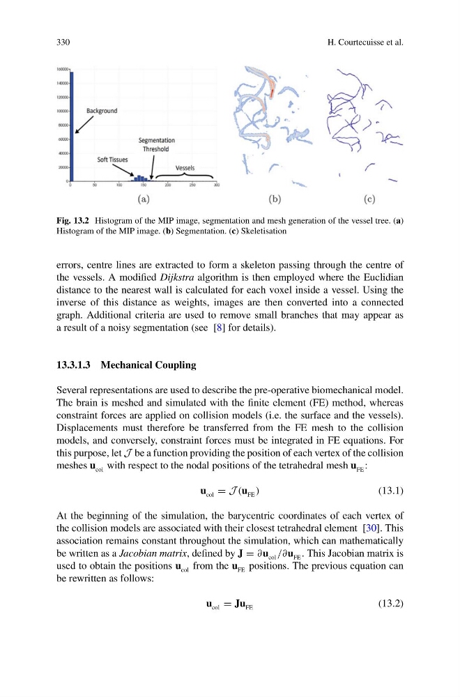
Fig. 13.2 Histogram of the MIP image, segmentation and mesh generation of the vessel tree. (a)
Histogram of the MIP image. (b) Segmentation. (c) Skeletisation
errors, centre lines are extracted to form a skeleton passing through the centre of
the vessels. A modified Dijkstra algorithm is then employed where the Euclidian
distance to the nearest wall is calculated for each voxel inside a vessel. Using the
inverse of this distance as weights, images are then converted into a connected
graph. Additional criteria are used to remove small branches that may appear as
a result of a noisy segmentation (see [8] for details).
13.3.1.3 Mechanical Coupling
Several representations are used to describe the pre-operative biomechanical model.
The brain is meshed and simulated with the finite element (FE) method, whereas
constraint forces are applied on collision models (i.e. the surface and the vessels).
Displacements must therefore be transferred from the FE mesh to the collision
models, and conversely, constraint forces must be integrated in FE equations. For
this purpose, let J be a function providing the position of each vertex of the collision
meshes u col with respect to the nodal positions of the tetrahedral mesh u FE :
u col = J (u FE )
(13.1)
At the beginning of the simulation, the barycentric coordinates of each vertex of
the collision models are associated with their closest tetrahedral element [30]. This
association remains constant throughout the simulation, which can mathematically
be written as a Jacobian matrix, defined by J = ∂u col /∂u FE . This Jacobian matrix is
used to obtain the positions u col from the u FE positions. The previous equation can
be rewritten as follows:
u col = Ju FE
(13.2)
H. Courtecuisse et al.
Fig. 13.2 Histogram of the MIP image, segmentation and mesh generation of the vessel tree. (a)
Histogram of the MIP image. (b) Segmentation. (c) Skeletisation
errors, centre lines are extracted to form a skeleton passing through the centre of
the vessels. A modified Dijkstra algorithm is then employed where the Euclidian
distance to the nearest wall is calculated for each voxel inside a vessel. Using the
inverse of this distance as weights, images are then converted into a connected
graph. Additional criteria are used to remove small branches that may appear as
a result of a noisy segmentation (see [8] for details).
13.3.1.3 Mechanical Coupling
Several representations are used to describe the pre-operative biomechanical model.
The brain is meshed and simulated with the finite element (FE) method, whereas
constraint forces are applied on collision models (i.e. the surface and the vessels).
Displacements must therefore be transferred from the FE mesh to the collision
models, and conversely, constraint forces must be integrated in FE equations. For
this purpose, let J be a function providing the position of each vertex of the collision
meshes u col with respect to the nodal positions of the tetrahedral mesh u FE :
u col = J (u FE )
(13.1)
At the beginning of the simulation, the barycentric coordinates of each vertex of
the collision models are associated with their closest tetrahedral element [30]. This
association remains constant throughout the simulation, which can mathematically
be written as a Jacobian matrix, defined by J = ∂u col /∂u FE . This Jacobian matrix is
used to obtain the positions u col from the u FE positions. The previous equation can
be rewritten as follows:
u col = Ju FE
(13.2)