

7 Biomechanical Modelling of the Brain for Neuronavigation in Epilepsy Surgery
173
7.2.4 Loading
We load the model through imposed displacements on the model surface (see
Chap. 6 and [27]). In intra-operative CT (Fig. 7.1c), the implanted electrodes,
and the grid which define the deformed surface of the brain, are clearly visible.
Rigid alignment of pre-operative MRI with intra-operative CT and projection of
the electrode positions onto the deformed brain surface (seen on CT) from the
undeformed brain surface (seen on the pre-operative MRI) allow precise definition
of surface displacements [23].
Using the intra-operative and pre-operative electrode coordinates, we define
a B-spline transform using the Scattered Transform 1 module in 3D Slicer. The
B-spline transform interpolates the difference between the intra-operative and preoperative electrode coordinates across all points within the node set defined in
HyperMesh. This allows us to calculate an approximation of the intra-operative
position of the surface nodes in the brain mesh. To apply the transform, the INP
file containing the node set coordinates is first converted into a VTK format so
that it can be read into 3D Slicer. Once transformed, the data is converted back
to a text-based or csv format so that it can be read into MATLAB for processing.
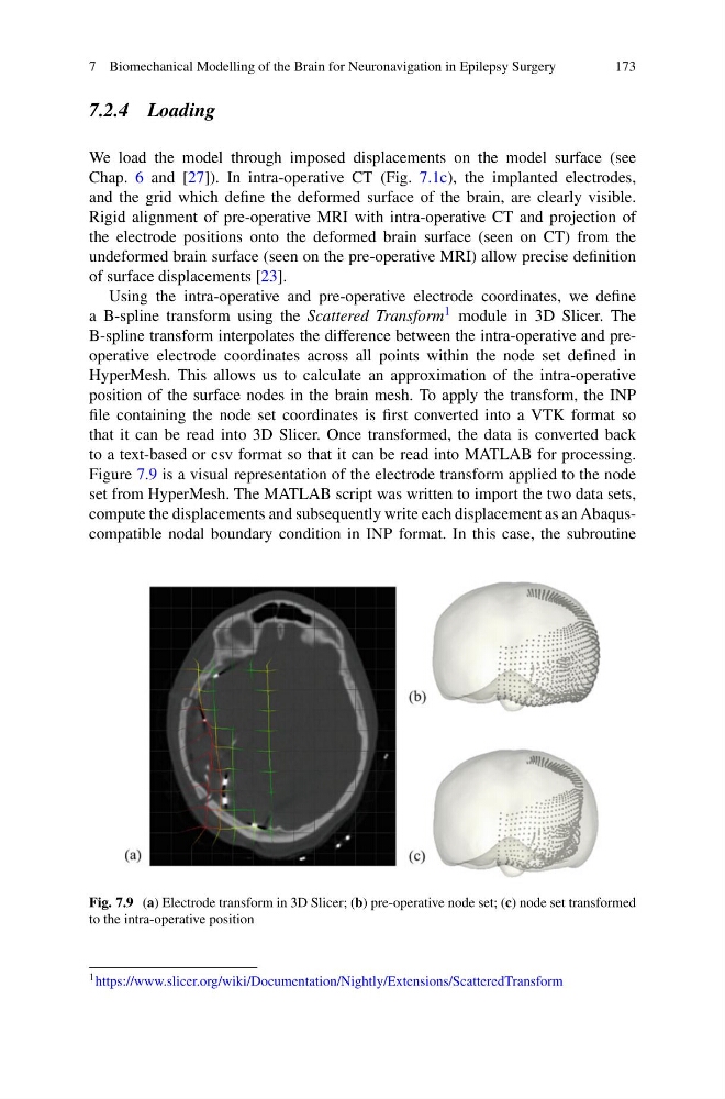
Figure 7.9 is a visual representation of the electrode transform applied to the node
set from HyperMesh. The MATLAB script was written to import the two data sets,
compute the displacements and subsequently write each displacement as an Abaquscompatible nodal boundary condition in INP format. In this case, the subroutine
Fig. 7.9 (a) Electrode transform in 3D Slicer; (b) pre-operative node set; (c) node set transformed
to the intra-operative position
1 https://www.slicer.org/wiki/Documentation/Nightly/Extensions/ScatteredTransform
173
7.2.4 Loading
We load the model through imposed displacements on the model surface (see
Chap. 6 and [27]). In intra-operative CT (Fig. 7.1c), the implanted electrodes,
and the grid which define the deformed surface of the brain, are clearly visible.
Rigid alignment of pre-operative MRI with intra-operative CT and projection of
the electrode positions onto the deformed brain surface (seen on CT) from the
undeformed brain surface (seen on the pre-operative MRI) allow precise definition
of surface displacements [23].
Using the intra-operative and pre-operative electrode coordinates, we define
a B-spline transform using the Scattered Transform 1 module in 3D Slicer. The
B-spline transform interpolates the difference between the intra-operative and preoperative electrode coordinates across all points within the node set defined in
HyperMesh. This allows us to calculate an approximation of the intra-operative
position of the surface nodes in the brain mesh. To apply the transform, the INP
file containing the node set coordinates is first converted into a VTK format so
that it can be read into 3D Slicer. Once transformed, the data is converted back
to a text-based or csv format so that it can be read into MATLAB for processing.
Figure 7.9 is a visual representation of the electrode transform applied to the node
set from HyperMesh. The MATLAB script was written to import the two data sets,
compute the displacements and subsequently write each displacement as an Abaquscompatible nodal boundary condition in INP format. In this case, the subroutine
Fig. 7.9 (a) Electrode transform in 3D Slicer; (b) pre-operative node set; (c) node set transformed
to the intra-operative position
1 https://www.slicer.org/wiki/Documentation/Nightly/Extensions/ScatteredTransform