

6 Biomechanical Modelling of the Brain for Neurosurgical Simulation. . .
155
-20
1
7
8
5
4
2
-20
-30
-30
-40
-40
-40
-40
-140
-120
-100
-80
-50
-50
-50
-60
-60
-60
-70
-70
-70
-80
-90
-20
-120
-100
-80
110
100
90
80
70
60
50
40
40
30
20
10
0
50
60
-60
-60
-40
-20
0
0
2 0
150
140
130
120
110
100
90
80
80
70
60
50
40
30
20
0
40
x (mm)
x (mm)
x (mm)
y (mm)
y (mm)
y (mm)
y (mm)
y (mm)
y (mm)
x (mm)
x (mm)
x (mm)
Biomechanics
Biomechanics
BSpline
Biomechanics
BSpline
BSpline
Biomechanics
BSpline
Biomechanics
BSpline
Biomechanics
BSpline
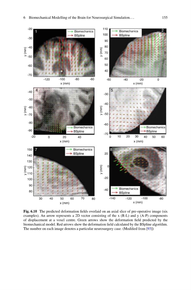
Fig. 6.10 The predicted deformation fields overlaid on an axial slice of pre-operative image (six
examples). An arrow represents a 2D vector consisting of the x (R-L) and y (A-P) components
of displacement at a voxel centre. Green arrows show the deformation field predicted by the
biomechanical model. Red arrows show the deformation field calculated by the BSpline algorithm.
The number on each image denotes a particular neurosurgery case. (Modified from [93])
155
-20
1
7
8
5
4
2
-20
-30
-30
-40
-40
-40
-40
-140
-120
-100
-80
-50
-50
-50
-60
-60
-60
-70
-70
-70
-80
-90
-20
-120
-100
-80
110
100
90
80
70
60
50
40
40
30
20
10
0
50
60
-60
-60
-40
-20
0
0
2 0
150
140
130
120
110
100
90
80
80
70
60
50
40
30
20
0
40
x (mm)
x (mm)
x (mm)
y (mm)
y (mm)
y (mm)
y (mm)
y (mm)
y (mm)
x (mm)
x (mm)
x (mm)
Biomechanics
Biomechanics
BSpline
Biomechanics
BSpline
BSpline
Biomechanics
BSpline
Biomechanics
BSpline
Biomechanics
BSpline
Fig. 6.10 The predicted deformation fields overlaid on an axial slice of pre-operative image (six
examples). An arrow represents a 2D vector consisting of the x (R-L) and y (A-P) components
of displacement at a voxel centre. Green arrows show the deformation field predicted by the
biomechanical model. Red arrows show the deformation field calculated by the BSpline algorithm.
The number on each image denotes a particular neurosurgery case. (Modified from [93])