

138
7 Modeling of the Optical Characteristics Fibrillar Structure
It should be noted that, to better match the real structure of the object under
investigation, the interfaces between the layers are represented by wavy surface
z i = H i (x, y), i = 1, 3.
Let a plane s- or p-polarized wave be incident to a layer at an angle θ . The reflected
field must be found. We consider only the case of the p polarization.
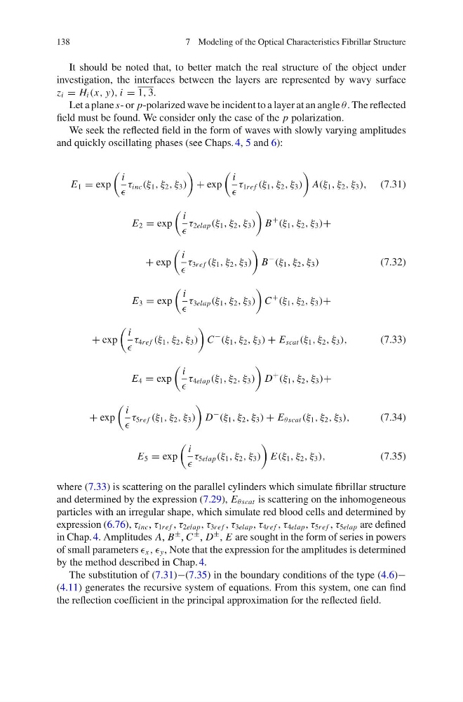
We seek the reflected field in the form of waves with slowly varying amplitudes
and quickly oscillating phases (see Chaps. 4, 5 and 6):
E 1 = exp
i
τ inc (ξ 1 , ξ 2 , ξ 3 )
+ exp
i
τ 1re f (ξ 1 , ξ 2 , ξ 3 )
A(ξ 1 , ξ 2 , ξ 3 ), (7.31)
E 2 = exp
i
τ 2elap (ξ 1 , ξ 2 , ξ 3 )
B
+
(ξ 1 , ξ 2 , ξ 3 )+
+ exp
i
τ 3re f (ξ 1 , ξ 2 , ξ 3 )
B
−
(ξ 1 , ξ 2 , ξ 3 )
(7.32)
E 3 = exp
i
τ 3elap (ξ 1 , ξ 2 , ξ 3 )
C
+
(ξ 1 , ξ 2 , ξ 3 )+
+ exp
i
τ 4re f (ξ 1 , ξ 2 , ξ 3 )
C
−
(ξ 1 , ξ 2 , ξ 3 ) + E scat (ξ 1 , ξ 2 , ξ 3 ),
(7.33)
E 4 = exp
i
τ 4elap (ξ 1 , ξ 2 , ξ 3 )
D
+
(ξ 1 , ξ 2 , ξ 3 )+
+ exp
i
τ 5re f (ξ 1 , ξ 2 , ξ 3 )
D
−
(ξ 1 , ξ 2 , ξ 3 ) + E θscat (ξ 1 , ξ 2 , ξ 3 ),
(7.34)
E 5 = exp
i
τ 5elap (ξ 1 , ξ 2 , ξ 3 )
E(ξ 1 , ξ 2 , ξ 3 ),
(7.35)
where (7.33) is scattering on the parallel cylinders which simulate fibrillar structure
and determined by the expression (7.29), E θscat is scattering on the inhomogeneous
particles with an irregular shape, which simulate red blood cells and determined by
expression (6.76), τ inc , τ 1re f , τ 2elap , τ 3re f , τ 3elap , τ 4re f , τ 4elap , τ 5re f , τ 5elap are defined
in Chap. 4. Amplitudes A, B
± , C
± , D
± , E are sought in the form of series in powers
of small parameters x , , y , Note that the expression for the amplitudes is determined
by the method described in Chap. 4.
The substitution of (7.31)−(7.35) in the boundary conditions of the type (4.6)−
(4.11) generates the recursive system of equations. From this system, one can find
the reflection coefficient in the principal approximation for the reflected field.
7 Modeling of the Optical Characteristics Fibrillar Structure
It should be noted that, to better match the real structure of the object under
investigation, the interfaces between the layers are represented by wavy surface
z i = H i (x, y), i = 1, 3.
Let a plane s- or p-polarized wave be incident to a layer at an angle θ . The reflected
field must be found. We consider only the case of the p polarization.
We seek the reflected field in the form of waves with slowly varying amplitudes
and quickly oscillating phases (see Chaps. 4, 5 and 6):
E 1 = exp
i
τ inc (ξ 1 , ξ 2 , ξ 3 )
+ exp
i
τ 1re f (ξ 1 , ξ 2 , ξ 3 )
A(ξ 1 , ξ 2 , ξ 3 ), (7.31)
E 2 = exp
i
τ 2elap (ξ 1 , ξ 2 , ξ 3 )
B
+
(ξ 1 , ξ 2 , ξ 3 )+
+ exp
i
τ 3re f (ξ 1 , ξ 2 , ξ 3 )
B
−
(ξ 1 , ξ 2 , ξ 3 )
(7.32)
E 3 = exp
i
τ 3elap (ξ 1 , ξ 2 , ξ 3 )
C
+
(ξ 1 , ξ 2 , ξ 3 )+
+ exp
i
τ 4re f (ξ 1 , ξ 2 , ξ 3 )
C
−
(ξ 1 , ξ 2 , ξ 3 ) + E scat (ξ 1 , ξ 2 , ξ 3 ),
(7.33)
E 4 = exp
i
τ 4elap (ξ 1 , ξ 2 , ξ 3 )
D
+
(ξ 1 , ξ 2 , ξ 3 )+
+ exp
i
τ 5re f (ξ 1 , ξ 2 , ξ 3 )
D
−
(ξ 1 , ξ 2 , ξ 3 ) + E θscat (ξ 1 , ξ 2 , ξ 3 ),
(7.34)
E 5 = exp
i
τ 5elap (ξ 1 , ξ 2 , ξ 3 )
E(ξ 1 , ξ 2 , ξ 3 ),
(7.35)
where (7.33) is scattering on the parallel cylinders which simulate fibrillar structure
and determined by the expression (7.29), E θscat is scattering on the inhomogeneous
particles with an irregular shape, which simulate red blood cells and determined by
expression (6.76), τ inc , τ 1re f , τ 2elap , τ 3re f , τ 3elap , τ 4re f , τ 4elap , τ 5re f , τ 5elap are defined
in Chap. 4. Amplitudes A, B
± , C
± , D
± , E are sought in the form of series in powers
of small parameters x , , y , Note that the expression for the amplitudes is determined
by the method described in Chap. 4.
The substitution of (7.31)−(7.35) in the boundary conditions of the type (4.6)−
(4.11) generates the recursive system of equations. From this system, one can find
the reflection coefficient in the principal approximation for the reflected field.