

5.4 Reflection of a Plane Wave from a Layer with Allowance for Surface Roughness
97
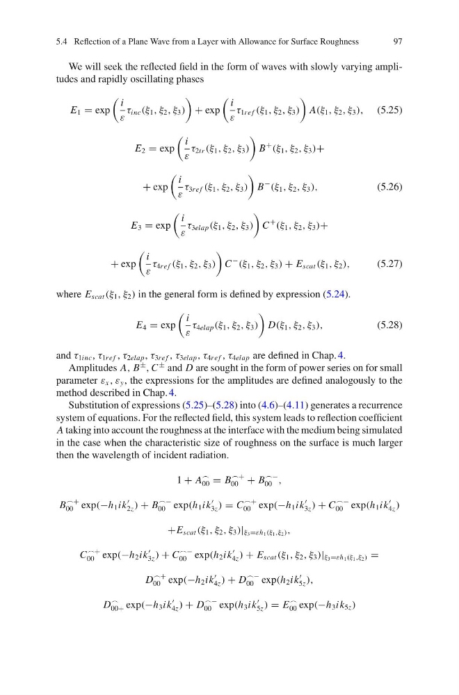
We will seek the reflected field in the form of waves with slowly varying amplitudes and rapidly oscillating phases
E 1 = exp
i
ε
τ inc (ξ 1 , ξ 2 , ξ 3 )
+ exp
i
ε
τ 1re f (ξ 1 , ξ 2 , ξ 3 )
A(ξ 1 , ξ 2 , ξ 3 ), (5.25)
E 2 = exp
i
ε
τ 2tr (ξ 1 , ξ 2 , ξ 3 )
B
+
(ξ 1 , ξ 2 , ξ 3 )+
+ exp
i
ε
τ 3re f (ξ 1 , ξ 2 , ξ 3 )
B
−
(ξ 1 , ξ 2 , ξ 3 ),
(5.26)
E 3 = exp
i
ε
τ 3elap (ξ 1 , ξ 2 , ξ 3 )
C
+
(ξ 1 , ξ 2 , ξ 3 )+
+ exp
i
ε
τ 4re f (ξ 1 , ξ 2 , ξ 3 )
C
−
(ξ 1 , ξ 2 , ξ 3 ) + E scat (ξ 1 , ξ 2 ),
(5.27)
where E scat (ξ 1 , ξ 2 ) in the general form is defined by expression (5.24).
E 4 = exp
i
ε
τ 4elap (ξ 1 , ξ 2 , ξ 3 )
D(ξ 1 , ξ 2 , ξ 3 ),
(5.28)
and τ 1inc , τ 1re f , τ 2elap , τ 3re f , τ 3elap , τ 4re f , τ 4elap are defined in Chap. 4.
Amplitudes A, B
± , C
± and D are sought in the form of power series on for small
parameter ε x , ε y , the expressions for the amplitudes are defined analogously to the
method described in Chap. 4.
Substitution of expressions (5.25)–(5.28) into (4.6)–(4.11) generates a recurrence
system of equations. For the reflected field, this system leads to reflection coefficient
A taking into account the roughness at the interface with the medium being simulated
in the case when the characteristic size of roughness on the surface is much larger
then the wavelength of incident radiation.
1 + A
00 = B
+
00 + B
−
00 ,
B
+
00 exp(−h 1 ik
2z ) + B
−
00 exp(h 1 ik
3z ) = C
+
00 exp(−h 1 ik
3z ) + C
−
00 exp(h 1 ik
4z )
+E scat (ξ 1 , ξ 2 , ξ 3 )| ξ 3 =εh 1 (ξ 1 ,ξ 2 ) ,
C
+
00 exp(−h 2 ik
3z ) + C
−
00 exp(h 2 ik
4z ) + E scat (ξ 1 , ξ 2 , ξ 3 )| ξ 3 =εh 1 (ξ 1 ,ξ 2 ) =
D
+
00 exp(−h 2 ik
4z ) + D
−
00 exp(h 2 ik
5z ),
D
00+ exp(−h 3 ik
4z ) + D
−
00 exp(h 3 ik
5z ) = E
00 exp(−h 3 ik 5z )
97
We will seek the reflected field in the form of waves with slowly varying amplitudes and rapidly oscillating phases
E 1 = exp
i
ε
τ inc (ξ 1 , ξ 2 , ξ 3 )
+ exp
i
ε
τ 1re f (ξ 1 , ξ 2 , ξ 3 )
A(ξ 1 , ξ 2 , ξ 3 ), (5.25)
E 2 = exp
i
ε
τ 2tr (ξ 1 , ξ 2 , ξ 3 )
B
+
(ξ 1 , ξ 2 , ξ 3 )+
+ exp
i
ε
τ 3re f (ξ 1 , ξ 2 , ξ 3 )
B
−
(ξ 1 , ξ 2 , ξ 3 ),
(5.26)
E 3 = exp
i
ε
τ 3elap (ξ 1 , ξ 2 , ξ 3 )
C
+
(ξ 1 , ξ 2 , ξ 3 )+
+ exp
i
ε
τ 4re f (ξ 1 , ξ 2 , ξ 3 )
C
−
(ξ 1 , ξ 2 , ξ 3 ) + E scat (ξ 1 , ξ 2 ),
(5.27)
where E scat (ξ 1 , ξ 2 ) in the general form is defined by expression (5.24).
E 4 = exp
i
ε
τ 4elap (ξ 1 , ξ 2 , ξ 3 )
D(ξ 1 , ξ 2 , ξ 3 ),
(5.28)
and τ 1inc , τ 1re f , τ 2elap , τ 3re f , τ 3elap , τ 4re f , τ 4elap are defined in Chap. 4.
Amplitudes A, B
± , C
± and D are sought in the form of power series on for small
parameter ε x , ε y , the expressions for the amplitudes are defined analogously to the
method described in Chap. 4.
Substitution of expressions (5.25)–(5.28) into (4.6)–(4.11) generates a recurrence
system of equations. For the reflected field, this system leads to reflection coefficient
A taking into account the roughness at the interface with the medium being simulated
in the case when the characteristic size of roughness on the surface is much larger
then the wavelength of incident radiation.
1 + A
00 = B
+
00 + B
−
00 ,
B
+
00 exp(−h 1 ik
2z ) + B
−
00 exp(h 1 ik
3z ) = C
+
00 exp(−h 1 ik
3z ) + C
−
00 exp(h 1 ik
4z )
+E scat (ξ 1 , ξ 2 , ξ 3 )| ξ 3 =εh 1 (ξ 1 ,ξ 2 ) ,
C
+
00 exp(−h 2 ik
3z ) + C
−
00 exp(h 2 ik
4z ) + E scat (ξ 1 , ξ 2 , ξ 3 )| ξ 3 =εh 1 (ξ 1 ,ξ 2 ) =
D
+
00 exp(−h 2 ik
4z ) + D
−
00 exp(h 2 ik
5z ),
D
00+ exp(−h 3 ik
4z ) + D
−
00 exp(h 3 ik
5z ) = E
00 exp(−h 3 ik 5z )