

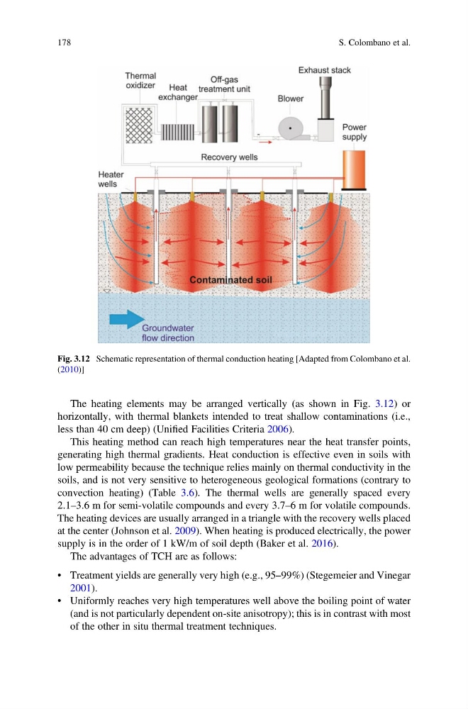
The heating elements may be arranged vertically (as shown in Fig. 3.12) or
horizontally, with thermal blankets intended to treat shallow contaminations (i.e.,
less than 40 cm deep) (Unified Facilities Criteria 2006).
This heating method can reach high temperatures near the heat transfer points,
generating high thermal gradients. Heat conduction is effective even in soils with
low permeability because the technique relies mainly on thermal conductivity in the
soils, and is not very sensitive to heterogeneous geological formations (contrary to
convection heating) (Table 3.6). The thermal wells are generally spaced every
2.1–3.6 m for semi-volatile compounds and every 3.7–6 m for volatile compounds.
The heating devices are usually arranged in a triangle with the recovery wells placed
at the center (Johnson et al. 2009). When heating is produced electrically, the power
supply is in the order of 1 kW/m of soil depth (Baker et al. 2016).
The advantages of TCH are as follows:
• Treatment yields are generally very high (e.g., 95–99%) (Stegemeier and Vinegar
2001).
• Uniformly reaches very high temperatures well above the boiling point of water
(and is not particularly dependent on-site anisotropy); this is in contrast with most
of the other in situ thermal treatment techniques.
Fig. 3.12 Schematic representation of thermal conduction heating [Adapted from Colombano et al.
(2010)]
178
S. Colombano et al.
horizontally, with thermal blankets intended to treat shallow contaminations (i.e.,
less than 40 cm deep) (Unified Facilities Criteria 2006).
This heating method can reach high temperatures near the heat transfer points,
generating high thermal gradients. Heat conduction is effective even in soils with
low permeability because the technique relies mainly on thermal conductivity in the
soils, and is not very sensitive to heterogeneous geological formations (contrary to
convection heating) (Table 3.6). The thermal wells are generally spaced every
2.1–3.6 m for semi-volatile compounds and every 3.7–6 m for volatile compounds.
The heating devices are usually arranged in a triangle with the recovery wells placed
at the center (Johnson et al. 2009). When heating is produced electrically, the power
supply is in the order of 1 kW/m of soil depth (Baker et al. 2016).
The advantages of TCH are as follows:
• Treatment yields are generally very high (e.g., 95–99%) (Stegemeier and Vinegar
2001).
• Uniformly reaches very high temperatures well above the boiling point of water
(and is not particularly dependent on-site anisotropy); this is in contrast with most
of the other in situ thermal treatment techniques.
Fig. 3.12 Schematic representation of thermal conduction heating [Adapted from Colombano et al.
(2010)]
178
S. Colombano et al.