

The Construction of Green Building …
43
Earth Work
and
Land Cleaning
Foundation
Construction
Placement of U-shape
Interlocking brick
(For supporting the Interlocking
Brick Wall)
Wall Construction
(Every 5-7 layers)
Placement of vertical
reinforcement bars
Strengthening
(Pouring the
grout for
strengthening the
wall system)
Electrical Conduit Installation
- Implementing PVC pipe
Finishing
Roofing
Installation
(after completion of
Interlocking Brick
Wall System)
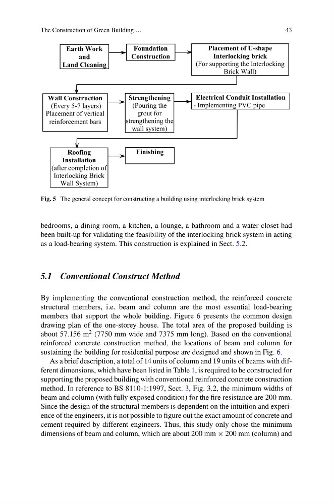
Fig. 5 The general concept for constructing a building using interlocking brick system
bedrooms, a dining room, a kitchen, a lounge, a bathroom and a water closet had
been built-up for validating the feasibility of the interlocking brick system in acting
as a load-bearing system. This construction is explained in Sect. 5.2.
5.1 Conventional Construct Method
By implementing the conventional construction method, the reinforced concrete
structural members, i.e. beam and column are the most essential load-bearing
members that support the whole building. Figure 6 presents the common design
drawing plan of the one-storey house. The total area of the proposed building is
about 57.156 m
2 (7750 mm wide and 7375 mm long). Based on the conventional
reinforced concrete construction method, the locations of beam and column for
sustaining the building for residential purpose are designed and shown in Fig. 6.
As a brief description, a total of 14 units of column and 19 units of beams with different dimensions, which have been listed in Table 1, is required to be constructed for
supporting the proposed building with conventional reinforced concrete construction
method. In reference to BS 8110-1:1997, Sect. 3, Fig. 3.2, the minimum widths of
beam and column (with fully exposed condition) for the fire resistance are 200 mm.
Since the design of the structural members is dependent on the intuition and experience of the engineers, it is not possible to figure out the exact amount of concrete and
cement required by different engineers. Thus, this study only chose the minimum
dimensions of beam and column, which are about 200 mm × 200 mm (column) and
43
Earth Work
and
Land Cleaning
Foundation
Construction
Placement of U-shape
Interlocking brick
(For supporting the Interlocking
Brick Wall)
Wall Construction
(Every 5-7 layers)
Placement of vertical
reinforcement bars
Strengthening
(Pouring the
grout for
strengthening the
wall system)
Electrical Conduit Installation
- Implementing PVC pipe
Finishing
Roofing
Installation
(after completion of
Interlocking Brick
Wall System)
Fig. 5 The general concept for constructing a building using interlocking brick system
bedrooms, a dining room, a kitchen, a lounge, a bathroom and a water closet had
been built-up for validating the feasibility of the interlocking brick system in acting
as a load-bearing system. This construction is explained in Sect. 5.2.
5.1 Conventional Construct Method
By implementing the conventional construction method, the reinforced concrete
structural members, i.e. beam and column are the most essential load-bearing
members that support the whole building. Figure 6 presents the common design
drawing plan of the one-storey house. The total area of the proposed building is
about 57.156 m
2 (7750 mm wide and 7375 mm long). Based on the conventional
reinforced concrete construction method, the locations of beam and column for
sustaining the building for residential purpose are designed and shown in Fig. 6.
As a brief description, a total of 14 units of column and 19 units of beams with different dimensions, which have been listed in Table 1, is required to be constructed for
supporting the proposed building with conventional reinforced concrete construction
method. In reference to BS 8110-1:1997, Sect. 3, Fig. 3.2, the minimum widths of
beam and column (with fully exposed condition) for the fire resistance are 200 mm.
Since the design of the structural members is dependent on the intuition and experience of the engineers, it is not possible to figure out the exact amount of concrete and
cement required by different engineers. Thus, this study only chose the minimum
dimensions of beam and column, which are about 200 mm × 200 mm (column) and