

For tall cells, the profile is presented such that the cell surface is
nearly perpendicular to the beam. This is not the case for flat cells or
bacteria, where the surface is much more oblique (compare Fig. 5h,
i). The tall profile can lead to issues with insufficient GIS platinum
deposition that would otherwise be acceptable. These cells may
require a longer GIS platinum deposition time and rotating the
stage to optimize deposition thickness.
Broken Lamellae
at the TEM
The finished lamellae are relatively fragile and are susceptible to
damage from rough handling. Slightly increasing the GIS platinum
deposition time may prove extra support and make handling easier.
It is important to only handle lamellae grids by the very edge of the
autogrid support. Another option is to reduce the width of the
lamellae to make them less susceptible to breakage.
Lamella Appears to Bend
during Milling
Recent reports have suggested that lamella bending can be attributed to tension in the bulk material arising from the vitrification
process. The proposed solution is to mill additional “micro-expansion joints” near the lamella to reduce the impact of surrounding
material motion [43]. In our hands, the micro-expansion joints also
reduce bending and subsequent breaking at the TEM. Silicon
dioxide grids may also offer a stiffer support that may reduce
lamella bending or breaking [47].
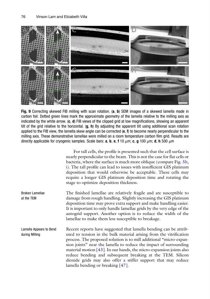
Fig. 9 Correcting skewed FIB milling with scan rotation. (a, b) SEM images of a skewed lamella made in
carbon foil. Dotted green lines mark the approximate geometry of the lamella relative to the milling axis as
indicated by the white arrow. (c, d) FIB views of the clipped grid at low magnifications, showing an apparent
tilt of the grid relative to the horizontal. (g, h) By adjusting the apparent tilt using additional scan rotation
applied to the FIB view, the lamella skew angle can be corrected (e, f) to become nearly perpendicular to the
milling axis. These demonstrative lamellae were milled on a room temperature carbon film grid. Results are
directly applicable for cryogenic samples. Scale bars: a, b, e, f 10 μm; c, g 100 μm; d, h 500 μm
76
Vinson Lam and Elizabeth Villa
nearly perpendicular to the beam. This is not the case for flat cells or
bacteria, where the surface is much more oblique (compare Fig. 5h,
i). The tall profile can lead to issues with insufficient GIS platinum
deposition that would otherwise be acceptable. These cells may
require a longer GIS platinum deposition time and rotating the
stage to optimize deposition thickness.
Broken Lamellae
at the TEM
The finished lamellae are relatively fragile and are susceptible to
damage from rough handling. Slightly increasing the GIS platinum
deposition time may prove extra support and make handling easier.
It is important to only handle lamellae grids by the very edge of the
autogrid support. Another option is to reduce the width of the
lamellae to make them less susceptible to breakage.
Lamella Appears to Bend
during Milling
Recent reports have suggested that lamella bending can be attributed to tension in the bulk material arising from the vitrification
process. The proposed solution is to mill additional “micro-expansion joints” near the lamella to reduce the impact of surrounding
material motion [43]. In our hands, the micro-expansion joints also
reduce bending and subsequent breaking at the TEM. Silicon
dioxide grids may also offer a stiffer support that may reduce
lamella bending or breaking [47].
Fig. 9 Correcting skewed FIB milling with scan rotation. (a, b) SEM images of a skewed lamella made in
carbon foil. Dotted green lines mark the approximate geometry of the lamella relative to the milling axis as
indicated by the white arrow. (c, d) FIB views of the clipped grid at low magnifications, showing an apparent
tilt of the grid relative to the horizontal. (g, h) By adjusting the apparent tilt using additional scan rotation
applied to the FIB view, the lamella skew angle can be corrected (e, f) to become nearly perpendicular to the
milling axis. These demonstrative lamellae were milled on a room temperature carbon film grid. Results are
directly applicable for cryogenic samples. Scale bars: a, b, e, f 10 μm; c, g 100 μm; d, h 500 μm
76
Vinson Lam and Elizabeth Villa