

If correctly calculated with compensation for the tilt, a better power spectrum
can be calculated (Fig. 8.3c, e). Xiong et al. [46] describe an adjustment to the
power spectra from tiles at different heights to compensate for the focal gradient.
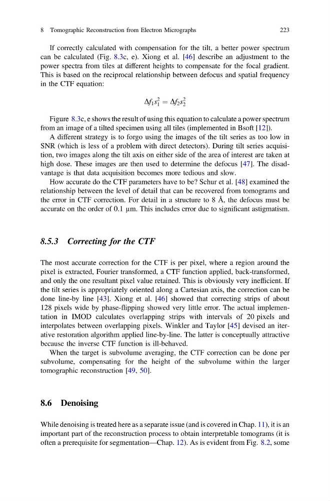
This is based on the reciprocal relationship between defocus and spatial frequency
in the CTF equation:
Df 1 s
2
1 ¼ Df 2 s
2
2
Figure 8.3c, e shows the result of using this equation to calculate a power spectrum
from an image of a tilted specimen using all tiles (implemented in Bsoft [12]).
A different strategy is to forgo using the images of the tilt series as too low in
SNR (which is less of a problem with direct detectors). During tilt series acquisition, two images along the tilt axis on either side of the area of interest are taken at
high dose. These images are then used to determine the defocus [47]. The disadvantage is that data acquisition becomes more tedious and slow.
How accurate do the CTF parameters have to be? Schur et al. [48] examined the
relationship between the level of detail that can be recovered from tomograms and
the error in CTF correction. For detail in a structure to 8 Å, the defocus must be
accurate on the order of 0.1 µm. This includes error due to significant astigmatism.
8.5.3 Correcting for the CTF
The most accurate correction for the CTF is per pixel, where a region around the
pixel is extracted, Fourier transformed, a CTF function applied, back-transformed,
and only the one resultant pixel value retained. This is obviously very inefficient. If
the tilt series is appropriately oriented along a Cartesian axis, the correction can be
done line-by line [43]. Xiong et al. [46] showed that correcting strips of about
128 pixels wide by phase-flipping showed very little error. The actual implementation in IMOD calculates overlapping strips with intervals of 20 pixels and
interpolates between overlapping pixels. Winkler and Taylor [45] devised an iterative restoration algorithm applied line-by-line. The latter is conceptually attractive
because the inverse CTF function is ill-behaved.
When the target is subvolume averaging, the CTF correction can be done per
subvolume, compensating for the height of the subvolume within the larger
tomographic reconstruction [49, 50].
8.6 Denoising
While denoising is treated here as a separate issue (and is covered in Chap. 11), it is an
important part of the reconstruction process to obtain interpretable tomograms (it is
often a prerequisite for segmentation—Chap. 12). As is evident from Fig. 8.2, some
8 Tomographic Reconstruction from Electron Micrographs
223
can be calculated (Fig. 8.3c, e). Xiong et al. [46] describe an adjustment to the
power spectra from tiles at different heights to compensate for the focal gradient.
This is based on the reciprocal relationship between defocus and spatial frequency
in the CTF equation:
Df 1 s
2
1 ¼ Df 2 s
2
2
Figure 8.3c, e shows the result of using this equation to calculate a power spectrum
from an image of a tilted specimen using all tiles (implemented in Bsoft [12]).
A different strategy is to forgo using the images of the tilt series as too low in
SNR (which is less of a problem with direct detectors). During tilt series acquisition, two images along the tilt axis on either side of the area of interest are taken at
high dose. These images are then used to determine the defocus [47]. The disadvantage is that data acquisition becomes more tedious and slow.
How accurate do the CTF parameters have to be? Schur et al. [48] examined the
relationship between the level of detail that can be recovered from tomograms and
the error in CTF correction. For detail in a structure to 8 Å, the defocus must be
accurate on the order of 0.1 µm. This includes error due to significant astigmatism.
8.5.3 Correcting for the CTF
The most accurate correction for the CTF is per pixel, where a region around the
pixel is extracted, Fourier transformed, a CTF function applied, back-transformed,
and only the one resultant pixel value retained. This is obviously very inefficient. If
the tilt series is appropriately oriented along a Cartesian axis, the correction can be
done line-by line [43]. Xiong et al. [46] showed that correcting strips of about
128 pixels wide by phase-flipping showed very little error. The actual implementation in IMOD calculates overlapping strips with intervals of 20 pixels and
interpolates between overlapping pixels. Winkler and Taylor [45] devised an iterative restoration algorithm applied line-by-line. The latter is conceptually attractive
because the inverse CTF function is ill-behaved.
When the target is subvolume averaging, the CTF correction can be done per
subvolume, compensating for the height of the subvolume within the larger
tomographic reconstruction [49, 50].
8.6 Denoising
While denoising is treated here as a separate issue (and is covered in Chap. 11), it is an
important part of the reconstruction process to obtain interpretable tomograms (it is
often a prerequisite for segmentation—Chap. 12). As is evident from Fig. 8.2, some
8 Tomographic Reconstruction from Electron Micrographs
223