

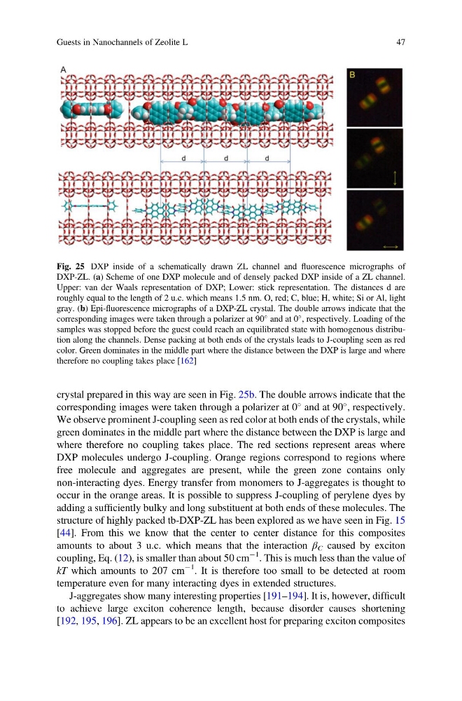
crystal prepared in this way are seen in Fig. 25b. The double arrows indicate that the
corresponding images were taken through a polarizer at 0
and at 90
, respectively.
We observe prominent J-coupling seen as red color at both ends of the crystals, while
green dominates in the middle part where the distance between the DXP is large and
where therefore no coupling takes place. The red sections represent areas where
DXP molecules undergo J-coupling. Orange regions correspond to regions where
free molecule and aggregates are present, while the green zone contains only
non-interacting dyes. Energy transfer from monomers to J-aggregates is thought to
occur in the orange areas. It is possible to suppress J-coupling of perylene dyes by
adding a sufficiently bulky and long substituent at both ends of these molecules. The
structure of highly packed tb-DXP-ZL has been explored as we have seen in Fig. 15
[44]. From this we know that the center to center distance for this composites
amounts to about 3 u.c. which means that the interaction β C caused by exciton
coupling, Eq. (12), is smaller than about 50 cm
À1 . This is much less than the value of
kT which amounts to 207 cm
À1 . It is therefore too small to be detected at room
temperature even for many interacting dyes in extended structures.
J-aggregates show many interesting properties [191–194]. It is, however, difficult
to achieve large exciton coherence length, because disorder causes shortening
[192, 195, 196]. ZL appears to be an excellent host for preparing exciton composites
Fig. 25 DXP inside of a schematically drawn ZL channel and fluorescence micrographs of
DXP-ZL. (a) Scheme of one DXP molecule and of densely packed DXP inside of a ZL channel.
Upper: van der Waals representation of DXP; Lower: stick representation. The distances d are
roughly equal to the length of 2 u.c. which means 1.5 nm. O, red; C, blue; H, white; Si or Al, light
gray. (b) Epi-fluorescence micrographs of a DXP-ZL crystal. The double arrows indicate that the
corresponding images were taken through a polarizer at 90
and at 0
, respectively. Loading of the
samples was stopped before the guest could reach an equilibrated state with homogenous distribution along the channels. Dense packing at both ends of the crystals leads to J-coupling seen as red
color. Green dominates in the middle part where the distance between the DXP is large and where
therefore no coupling takes place [162]
Guests in Nanochannels of Zeolite L
47
corresponding images were taken through a polarizer at 0
and at 90
, respectively.
We observe prominent J-coupling seen as red color at both ends of the crystals, while
green dominates in the middle part where the distance between the DXP is large and
where therefore no coupling takes place. The red sections represent areas where
DXP molecules undergo J-coupling. Orange regions correspond to regions where
free molecule and aggregates are present, while the green zone contains only
non-interacting dyes. Energy transfer from monomers to J-aggregates is thought to
occur in the orange areas. It is possible to suppress J-coupling of perylene dyes by
adding a sufficiently bulky and long substituent at both ends of these molecules. The
structure of highly packed tb-DXP-ZL has been explored as we have seen in Fig. 15
[44]. From this we know that the center to center distance for this composites
amounts to about 3 u.c. which means that the interaction β C caused by exciton
coupling, Eq. (12), is smaller than about 50 cm
À1 . This is much less than the value of
kT which amounts to 207 cm
À1 . It is therefore too small to be detected at room
temperature even for many interacting dyes in extended structures.
J-aggregates show many interesting properties [191–194]. It is, however, difficult
to achieve large exciton coherence length, because disorder causes shortening
[192, 195, 196]. ZL appears to be an excellent host for preparing exciton composites
Fig. 25 DXP inside of a schematically drawn ZL channel and fluorescence micrographs of
DXP-ZL. (a) Scheme of one DXP molecule and of densely packed DXP inside of a ZL channel.
Upper: van der Waals representation of DXP; Lower: stick representation. The distances d are
roughly equal to the length of 2 u.c. which means 1.5 nm. O, red; C, blue; H, white; Si or Al, light
gray. (b) Epi-fluorescence micrographs of a DXP-ZL crystal. The double arrows indicate that the
corresponding images were taken through a polarizer at 90
and at 0
, respectively. Loading of the
samples was stopped before the guest could reach an equilibrated state with homogenous distribution along the channels. Dense packing at both ends of the crystals leads to J-coupling seen as red
color. Green dominates in the middle part where the distance between the DXP is large and where
therefore no coupling takes place [162]
Guests in Nanochannels of Zeolite L
47