

G
a
s
re
a
c
to
r
d
o
w
n
st
re
a
m
re
a
c
to
r
9/05
1/09
RIL 1/2
Water gauge
MDP level A/B
Soil gas sampler
RGBZ
MDP 6
V
Multilevel sampler I...V
MDP 7
Water gauge
Aquitard
RIL 1
(silt)
Soil gas
–12.0 m
IV
RIL 2
II
sampler
BIL 2/09
MDP A/B
I
Balance
zone I
–16.0 m
Balance
(plume fringe)
Unconfined
zone I
aquifer
(plume center)
7/05 proj.
(coarse sand)
Bottom layer
0
1 0
20 m
2/04 proj.
(lignite)
–22.0 m
Period of operatrion of the Profen gas PRB
5000
Sum of benzene, toluene, ethyl benzene, xylene (µg/L)
4500
Step I
Step II
Step III
Step IV
4000
Obs. well 2/04
3500
Plume center
upstream
3000
2500
2000
1500
Obs. well 1/09
1000
Plume center
500
downstream
0
Jun-10 Jul-10 Aug-10 Sep-10 Oct-10 Nov-10 Dec-10 Jan-11 Feb-11 Mar-11 Apr-11 May-11 Jun-11 Jul-11
208
Permeable Reactive Barrier
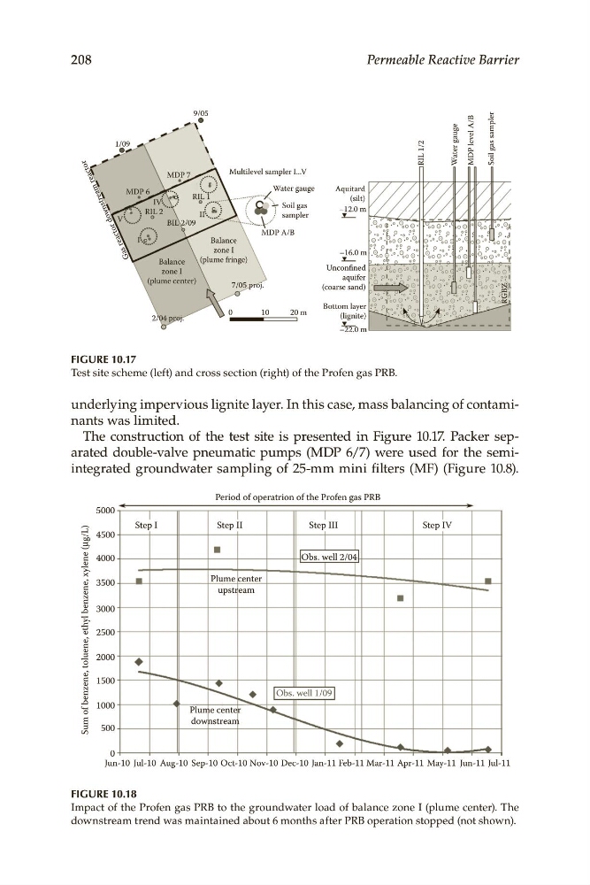
FIGURE 10.17
Test site scheme (left) and cross section (right) of the Profen gas PRB.
underlying impervious lignite layer. In this case, mass balancing of contaminants was limited.
The construction of the test site is presented in Figure 10.17. Packer separated double-valve pneumatic pumps (MDP 6/7) were used for the semiintegrated groundwater sampling of 25-mm mini filters (MF) (Figure 10.8).
FIGURE 10.18
Impact of the Profen gas PRB to the groundwater load of balance zone I (plume center). The
downstream trend was maintained about 6 months after PRB operation stopped (not shown).
a
s
re
a
c
to
r
d
o
w
n
st
re
a
m
re
a
c
to
r
9/05
1/09
RIL 1/2
Water gauge
MDP level A/B
Soil gas sampler
RGBZ
MDP 6
V
Multilevel sampler I...V
MDP 7
Water gauge
Aquitard
RIL 1
(silt)
Soil gas
–12.0 m
IV
RIL 2
II
sampler
BIL 2/09
MDP A/B
I
Balance
zone I
–16.0 m
Balance
(plume fringe)
Unconfined
zone I
aquifer
(plume center)
7/05 proj.
(coarse sand)
Bottom layer
0
1 0
20 m
2/04 proj.
(lignite)
–22.0 m
Period of operatrion of the Profen gas PRB
5000
Sum of benzene, toluene, ethyl benzene, xylene (µg/L)
4500
Step I
Step II
Step III
Step IV
4000
Obs. well 2/04
3500
Plume center
upstream
3000
2500
2000
1500
Obs. well 1/09
1000
Plume center
500
downstream
0
Jun-10 Jul-10 Aug-10 Sep-10 Oct-10 Nov-10 Dec-10 Jan-11 Feb-11 Mar-11 Apr-11 May-11 Jun-11 Jul-11
208
Permeable Reactive Barrier
FIGURE 10.17
Test site scheme (left) and cross section (right) of the Profen gas PRB.
underlying impervious lignite layer. In this case, mass balancing of contaminants was limited.
The construction of the test site is presented in Figure 10.17. Packer separated double-valve pneumatic pumps (MDP 6/7) were used for the semiintegrated groundwater sampling of 25-mm mini filters (MF) (Figure 10.8).
FIGURE 10.18
Impact of the Profen gas PRB to the groundwater load of balance zone I (plume center). The
downstream trend was maintained about 6 months after PRB operation stopped (not shown).