

Channelized coherent flow—
10,000 low/high-pressure injection: NDI/HDI
1000
100
Bench scale
gas injection rate (cm 3
/min)
100
Bubbly
incoherent flow
10
10
1
0.1
Pervasive incoherent flow—
low pressure injection: NDI
0.5
0.3/0.5
0.8/1.0 0.3/2
0.6/2
1.6/2
2.0/2.2
1
2
3
4
1
0.1
Sand
Main grain size (mm)
Gravel
Gas injection rate (m 3
/h)
field scale
186
Permeable Reactive Barrier
ceased. It can also lead to redistribution of subsurface gas storage. Effective
pervasive gas propagation is in the range of 10 −2 –10 −1 m/h.
When applying HDI, local increases in, as well as the homogenization of,
gas saturation are induced in a near region with an ROI <3 m (Geistlinger,
2010). In this case, gases can be effectively supplied to the bottom zone of
an aquifer (which is of special interest in unconfined aquifers), and when a
density-driven plume propagation is under consideration (e.g., a dissolved
CHC plume). With increasing distance and due to gas viscosity and compressibility characteristics, the HDI injection pressure transforms almost
completely into high gas propagation velocities in coherent channelized networks. There is no additional gas saturation effect of HDI at greater distances
from the injection point and the effective gas propagation of channelized
flow is of >1 × 10 0 m/h. A wide velocity range indicates the instability of this
transport behavior with a few dominating macroflow paths.
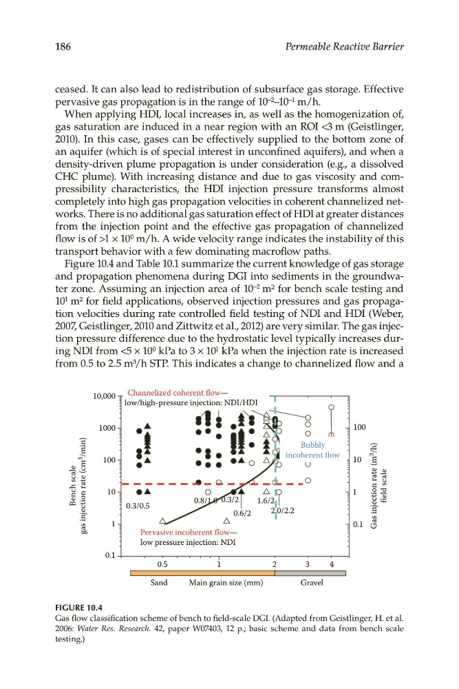
Figure 10.4 and Table 10.1 summarize the current knowledge of gas storage
and propagation phenomena during DGI into sediments in the groundwater zone. Assuming an injection area of 10 −2 m² for bench scale testing and
10 1 m² for field applications, observed injection pressures and gas propagation velocities during rate controlled field testing of NDI and HDI (Weber,
2007, Geistlinger, 2010 and Zittwitz et al., 2012) are very similar. The gas injection pressure difference due to the hydrostatic level typically increases during NDI from <5 × 10 0 kPa to 3 × 10 1 kPa when the injection rate is increased
from 0.5 to 2.5 m³/h STP. This indicates a change to channelized flow and a
FIGURE 10.4
Gas flow classification scheme of bench to field-scale DGI. (Adapted from Geistlinger, H. et al.
2006: Water Res. Research. 42, paper W07403, 12 p.; basic scheme and data from bench scale
testing.)
10,000 low/high-pressure injection: NDI/HDI
1000
100
Bench scale
gas injection rate (cm 3
/min)
100
Bubbly
incoherent flow
10
10
1
0.1
Pervasive incoherent flow—
low pressure injection: NDI
0.5
0.3/0.5
0.8/1.0 0.3/2
0.6/2
1.6/2
2.0/2.2
1
2
3
4
1
0.1
Sand
Main grain size (mm)
Gravel
Gas injection rate (m 3
/h)
field scale
186
Permeable Reactive Barrier
ceased. It can also lead to redistribution of subsurface gas storage. Effective
pervasive gas propagation is in the range of 10 −2 –10 −1 m/h.
When applying HDI, local increases in, as well as the homogenization of,
gas saturation are induced in a near region with an ROI <3 m (Geistlinger,
2010). In this case, gases can be effectively supplied to the bottom zone of
an aquifer (which is of special interest in unconfined aquifers), and when a
density-driven plume propagation is under consideration (e.g., a dissolved
CHC plume). With increasing distance and due to gas viscosity and compressibility characteristics, the HDI injection pressure transforms almost
completely into high gas propagation velocities in coherent channelized networks. There is no additional gas saturation effect of HDI at greater distances
from the injection point and the effective gas propagation of channelized
flow is of >1 × 10 0 m/h. A wide velocity range indicates the instability of this
transport behavior with a few dominating macroflow paths.
Figure 10.4 and Table 10.1 summarize the current knowledge of gas storage
and propagation phenomena during DGI into sediments in the groundwater zone. Assuming an injection area of 10 −2 m² for bench scale testing and
10 1 m² for field applications, observed injection pressures and gas propagation velocities during rate controlled field testing of NDI and HDI (Weber,
2007, Geistlinger, 2010 and Zittwitz et al., 2012) are very similar. The gas injection pressure difference due to the hydrostatic level typically increases during NDI from <5 × 10 0 kPa to 3 × 10 1 kPa when the injection rate is increased
from 0.5 to 2.5 m³/h STP. This indicates a change to channelized flow and a
FIGURE 10.4
Gas flow classification scheme of bench to field-scale DGI. (Adapted from Geistlinger, H. et al.
2006: Water Res. Research. 42, paper W07403, 12 p.; basic scheme and data from bench scale
testing.)