

56 Ground improvement by deep vibratory methods
Experience shows that a compacted free-draining granular soil has a relative density of at least 70% throughout, which is sufficient for foundation
purposes under normal conditions and that any subsequent ground motions
other than earthquakes are generally not strong enough to cause additional
settlement. In the case of seismic events and exceptionally strong impacts
from explosions or similar events, the induced energies can be extremely
high and a detailed study of the required density, which will often need to
be in excess of 85% relative density, becomes necessary (see Section 3.3.3).
As we saw earlier, the effectiveness of the vibro compaction process
decreases with increasing distance from the center of compaction, depending on a number of variables (vibrator characteristics, soil properties, operational modes). Figure 3.4b shows an idealized density profile for a single
vibro compaction point at a selected depth. The decrease from a maximum
in the neighborhood of the center is rather rapid at first, before it lessens
in an exponential way as the distance increases and the original density is
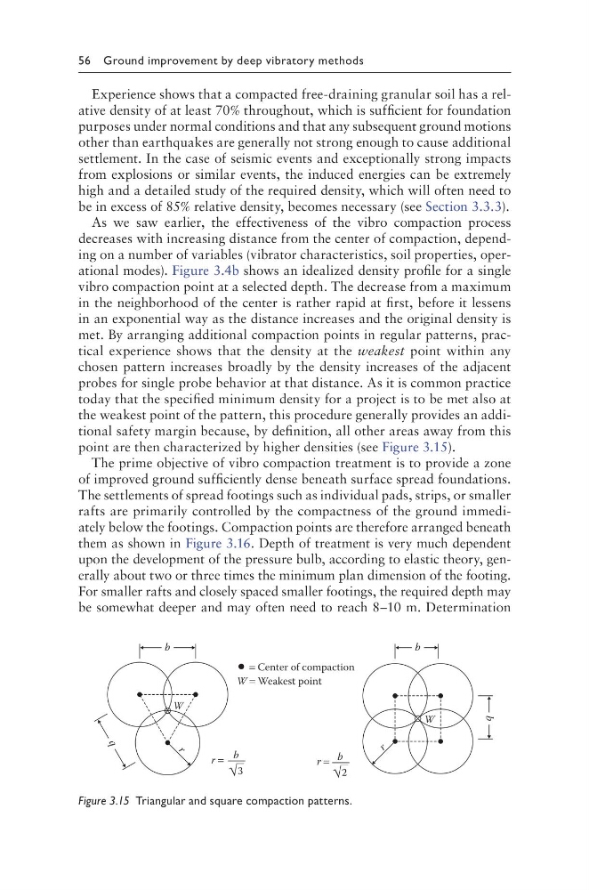
met. By arranging additional compaction points in regular patterns, practical experience shows that the density at the weakest point within any
chosen pattern increases broadly by the density increases of the adjacent
probes for single probe behavior at that distance. As it is common practice
today that the specified minimum density for a project is to be met also at
the weakest point of the pattern, this procedure generally provides an additional safety margin because, by definition, all other areas away from this
point are then characterized by higher densities (see Figure 3.15).
The prime objective of vibro compaction treatment is to provide a zone
of improved ground sufficiently dense beneath surface spread foundations.
The settlements of spread footings such as individual pads, strips, or smaller
rafts are primarily controlled by the compactness of the ground immediately below the footings. Compaction points are therefore arranged beneath
them as shown in Figure 3.16. Depth of treatment is very much dependent
upon the development of the pressure bulb, according to elastic theory, generally about two or three times the minimum plan dimension of the footing.
For smaller rafts and closely spaced smaller footings, the required depth may
be somewhat deeper and may often need to reach 8–10 m. Determination
r =
3
b
r =
2
b
W = Weakest point
W
W
r
b
= Center of compaction
b
r
b
b
Figure 3.15 Triangular and square compaction patterns.
Experience shows that a compacted free-draining granular soil has a relative density of at least 70% throughout, which is sufficient for foundation
purposes under normal conditions and that any subsequent ground motions
other than earthquakes are generally not strong enough to cause additional
settlement. In the case of seismic events and exceptionally strong impacts
from explosions or similar events, the induced energies can be extremely
high and a detailed study of the required density, which will often need to
be in excess of 85% relative density, becomes necessary (see Section 3.3.3).
As we saw earlier, the effectiveness of the vibro compaction process
decreases with increasing distance from the center of compaction, depending on a number of variables (vibrator characteristics, soil properties, operational modes). Figure 3.4b shows an idealized density profile for a single
vibro compaction point at a selected depth. The decrease from a maximum
in the neighborhood of the center is rather rapid at first, before it lessens
in an exponential way as the distance increases and the original density is
met. By arranging additional compaction points in regular patterns, practical experience shows that the density at the weakest point within any
chosen pattern increases broadly by the density increases of the adjacent
probes for single probe behavior at that distance. As it is common practice
today that the specified minimum density for a project is to be met also at
the weakest point of the pattern, this procedure generally provides an additional safety margin because, by definition, all other areas away from this
point are then characterized by higher densities (see Figure 3.15).
The prime objective of vibro compaction treatment is to provide a zone
of improved ground sufficiently dense beneath surface spread foundations.
The settlements of spread footings such as individual pads, strips, or smaller
rafts are primarily controlled by the compactness of the ground immediately below the footings. Compaction points are therefore arranged beneath
them as shown in Figure 3.16. Depth of treatment is very much dependent
upon the development of the pressure bulb, according to elastic theory, generally about two or three times the minimum plan dimension of the footing.
For smaller rafts and closely spaced smaller footings, the required depth may
be somewhat deeper and may often need to reach 8–10 m. Determination
r =
3
b
r =
2
b
W = Weakest point
W
W
r
b
= Center of compaction
b
r
b
b
Figure 3.15 Triangular and square compaction patterns.