

10 Ground improvement by deep vibratory methods
Efficient work on-site required the following from the vibrator:
• It should be capable of penetrating as quickly as possible to the
required depth.
• It should be possible to withdraw the vibrator without problems from
the ground during compaction.
• The vibratory effect should efficiently compact a zone in the soil
around the vibrator as large as possible.
A blueprint of a depth vibrator from 1937 (Figure 2.5) shows that it consisted of a 260 mm diameter, 2.0 m long, steel tube. In its interior, two electric motors of 12.5 kW each were placed on the upper part of the vertical
axis with up to three bob weights at the lower end. The upper part of the
vibrator consisted of a device for channeling water to a nozzle at the vibrator point, an inlet for the electric cable for the motors and mechanical features separating the vibratory motions created by the rotating bob weights
from the follower tubes carrying the vibrator and enabling its deep penetration into the ground. The motors rotated at 50 Hz resulting in 75 kN
horizontal force of the eccentric weights creating a double amplitude of
10 mm. The lifetime of the bearings posed a major problem at the time, but
the designers must have quickly succeeded in making the machine robust
enough for its use on-site, because in the following years many interesting
foundations were carried out with the vibro flotation method.
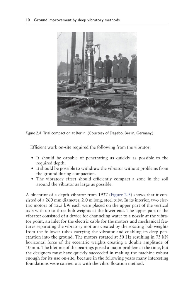
Figure 2.4 Trial compaction at Berlin. (Courtesy of Degebo, Berlin, Germany.)
Efficient work on-site required the following from the vibrator:
• It should be capable of penetrating as quickly as possible to the
required depth.
• It should be possible to withdraw the vibrator without problems from
the ground during compaction.
• The vibratory effect should efficiently compact a zone in the soil
around the vibrator as large as possible.
A blueprint of a depth vibrator from 1937 (Figure 2.5) shows that it consisted of a 260 mm diameter, 2.0 m long, steel tube. In its interior, two electric motors of 12.5 kW each were placed on the upper part of the vertical
axis with up to three bob weights at the lower end. The upper part of the
vibrator consisted of a device for channeling water to a nozzle at the vibrator point, an inlet for the electric cable for the motors and mechanical features separating the vibratory motions created by the rotating bob weights
from the follower tubes carrying the vibrator and enabling its deep penetration into the ground. The motors rotated at 50 Hz resulting in 75 kN
horizontal force of the eccentric weights creating a double amplitude of
10 mm. The lifetime of the bearings posed a major problem at the time, but
the designers must have quickly succeeded in making the machine robust
enough for its use on-site, because in the following years many interesting
foundations were carried out with the vibro flotation method.
Figure 2.4 Trial compaction at Berlin. (Courtesy of Degebo, Berlin, Germany.)