

182 Ground improvement by deep vibratory methods
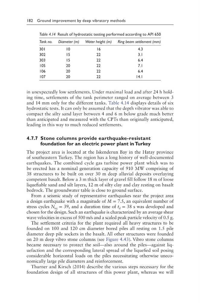
in unexpectedly low settlements. Under maximal load and after 24 h holding time, settlements of the tank perimeter ranged on average between 3
and 14 mm only for the different tanks. Table 4.14 displays details of six
hydrostatic tests. It can only be assumed that the depth vibrator was able to
compact the silty sand layer between 4 and 6 m below grade much better
than anticipated and measured with the CPTs than originally anticipated,
leading in this way to much reduced settlements.
4.7.7 Stone columns provide earthquake-resistant
foundation for an electric power plant in Turkey
The project area is located at the Iskenderun Bay in the Hatay province
of southeastern Turkey. The region has a long history of well-documented
earthquakes. The combined cycle gas turbine power plant which was to
be erected has a nominal generation capacity of 910 MW comprising of
38 structures to be built on over 30 m deep alluvial deposits overlaying
competent basalt. Below a 3 m thick layer of gravel fill follow 18 m of loose
liquefiable sand and silt layers, 12 m of silty clay and clay resting on basalt
bedrock. The groundwater table is close to ground surface.
From a seismic study of representative earthquakes near the project area
a design earthquake with a magnitude of M = 7.5, an equivalent number of
stress cycles N eq = 39, and a duration time of t d = 38 s was developed and
chosen for the design. Such an earthquake is characterized by an average shear
wave velocities in excess of 500 m/s and a scaled peak particle velocity of 0.5 g.
The settlement criteria for the plant required all heavy structures to be
founded on 100 and 120 cm diameter bored piles all resting on 1.5 pile
diameter deep pile sockets in the basalt. All other structures were founded
on 20 m deep vibro stone columns (see Figure 4.43). Vibro stone columns
became necessary to protect the soil—also around the piles—against liquefaction and the corresponding lateral spread of the liquefied soil posing
considerable horizontal loads on the piles necessitating otherwise uneconomically large pile diameters and reinforcement.
Thurner and Kirsch (2014) describe the various steps necessary for the
foundation design of all structures of this power plant, whereas we will
Table 4.14 Result of hydrostatic testing performed according to API 650
Tank no. Diameter (m) Water height (m) Ring beam settlement (mm)
301
10
16
4.3
302
15
22
3.1
303
15
22
6.4
105
20
22
7.1
106
20
22
6.4
107
20
22
14.1
in unexpectedly low settlements. Under maximal load and after 24 h holding time, settlements of the tank perimeter ranged on average between 3
and 14 mm only for the different tanks. Table 4.14 displays details of six
hydrostatic tests. It can only be assumed that the depth vibrator was able to
compact the silty sand layer between 4 and 6 m below grade much better
than anticipated and measured with the CPTs than originally anticipated,
leading in this way to much reduced settlements.
4.7.7 Stone columns provide earthquake-resistant
foundation for an electric power plant in Turkey
The project area is located at the Iskenderun Bay in the Hatay province
of southeastern Turkey. The region has a long history of well-documented
earthquakes. The combined cycle gas turbine power plant which was to
be erected has a nominal generation capacity of 910 MW comprising of
38 structures to be built on over 30 m deep alluvial deposits overlaying
competent basalt. Below a 3 m thick layer of gravel fill follow 18 m of loose
liquefiable sand and silt layers, 12 m of silty clay and clay resting on basalt
bedrock. The groundwater table is close to ground surface.
From a seismic study of representative earthquakes near the project area
a design earthquake with a magnitude of M = 7.5, an equivalent number of
stress cycles N eq = 39, and a duration time of t d = 38 s was developed and
chosen for the design. Such an earthquake is characterized by an average shear
wave velocities in excess of 500 m/s and a scaled peak particle velocity of 0.5 g.
The settlement criteria for the plant required all heavy structures to be
founded on 100 and 120 cm diameter bored piles all resting on 1.5 pile
diameter deep pile sockets in the basalt. All other structures were founded
on 20 m deep vibro stone columns (see Figure 4.43). Vibro stone columns
became necessary to protect the soil—also around the piles—against liquefaction and the corresponding lateral spread of the liquefied soil posing
considerable horizontal loads on the piles necessitating otherwise uneconomically large pile diameters and reinforcement.
Thurner and Kirsch (2014) describe the various steps necessary for the
foundation design of all structures of this power plant, whereas we will
Table 4.14 Result of hydrostatic testing performed according to API 650
Tank no. Diameter (m) Water height (m) Ring beam settlement (mm)
301
10
16
4.3
302
15
22
3.1
303
15
22
6.4
105
20
22
7.1
106
20
22
6.4
107
20
22
14.1