

176 Ground improvement by deep vibratory methods
including stone take. Early settlement measurements on the structures indicate that the performance is considerably better than expected and that the
design criteria were met.
4.7.4 High replacement vibro stone columns
for a port extension
The majority of vibro stone column contracts are performed at area
replacements of about 5%–30%. It is feasible to provide higher replacement
when higher bearing capacity, tighter settlement, or higher effective angle
Table 4.12 Evaluation of single column load tests
Test load 200 kN/m 2
Test 1
Test 2 Test 3 Test 4
Column dia. d c
m
0.6
0.5
0.6
0.5
Footing area A
m 2
1.56
1.56
4.0
4.0
a c = A c /A
–
0.18
0.13
0.07
0.05
Settlement s
mm
8
11.4
15.7
23.9
Equiv. diameter d e
m
1.41
1.41
2.26
2.26
Equiv. col. length l *
m
5.36
5.36
5.88
5.88
Equiv. modulus E*
MN/m 2 133.9
94.0
75.0
49.2
Grid area A (d c = 0.6 m)
m 2
1.56
2.17
4.0
5.65
Grid spacing a (d c = 0.6 m) m
1.25
1.47
2.0
2.38
a For square grid.
1
2
3
4
5
6
7
8
0
160
140
120
100
60
40
20
80
Grid area A (m
2 )
Without improvement E 0 = 8 MN/m
2
Required for design E d = 21 MN/m
2
Necessary grid area A n = 7.4 m
2
E d
E 0
E (MN/m
2
)
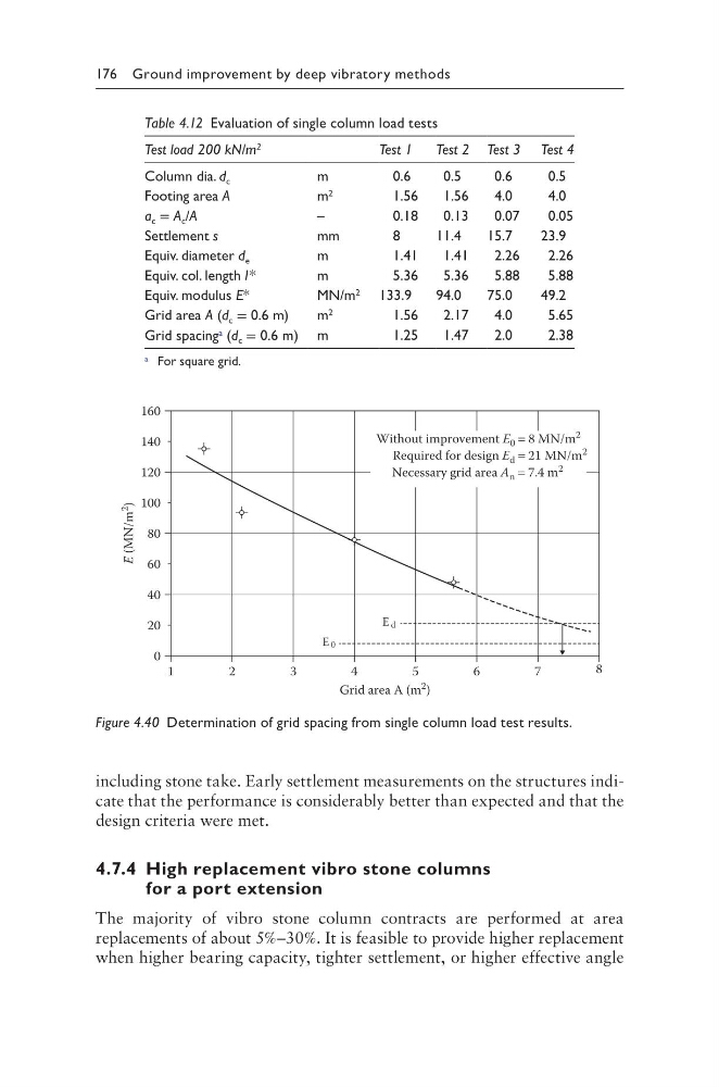
Figure 4.40 Determination of grid spacing from single column load test results.
including stone take. Early settlement measurements on the structures indicate that the performance is considerably better than expected and that the
design criteria were met.
4.7.4 High replacement vibro stone columns
for a port extension
The majority of vibro stone column contracts are performed at area
replacements of about 5%–30%. It is feasible to provide higher replacement
when higher bearing capacity, tighter settlement, or higher effective angle
Table 4.12 Evaluation of single column load tests
Test load 200 kN/m 2
Test 1
Test 2 Test 3 Test 4
Column dia. d c
m
0.6
0.5
0.6
0.5
Footing area A
m 2
1.56
1.56
4.0
4.0
a c = A c /A
–
0.18
0.13
0.07
0.05
Settlement s
mm
8
11.4
15.7
23.9
Equiv. diameter d e
m
1.41
1.41
2.26
2.26
Equiv. col. length l *
m
5.36
5.36
5.88
5.88
Equiv. modulus E*
MN/m 2 133.9
94.0
75.0
49.2
Grid area A (d c = 0.6 m)
m 2
1.56
2.17
4.0
5.65
Grid spacing a (d c = 0.6 m) m
1.25
1.47
2.0
2.38
a For square grid.
1
2
3
4
5
6
7
8
0
160
140
120
100
60
40
20
80
Grid area A (m
2 )
Without improvement E 0 = 8 MN/m
2
Required for design E d = 21 MN/m
2
Necessary grid area A n = 7.4 m
2
E d
E 0
E (MN/m
2
)
Figure 4.40 Determination of grid spacing from single column load test results.