

Improvement of fine-grained and cohesive soils 135
with γ c being the unit weight of the stone column material (use buoyant
weight in submerged condition) and n c representing the stress concentration
factor in the stone column at depth z.
The shear strength of the stone column follows then as
τ
σ
δ
ϕ
c
v ,c
c
= ′ ⋅
(
cos )tan
2
(4.30)
Vertical effective stress ′
σ v,s and shear stress τ s in the soil surrounding the
column are calculated from
′ = ⋅
⋅
σ
γ
σ
v,s
s
s
z n
+
(4.31)
and
τ
σ
δ
ϕ
s
v ,s
s
cos tan
= + ′ ⋅
c (
)
2
(4.32)
The weighted average unit weight γ avg of the reinforced unit cell is used to
calculate the acting moment.
γ
γ
γ
avg
c
c
s
s
= ⋅ + ⋅
a
a
(4.33)
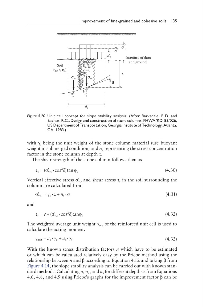
With the known stress distribution factors n which have to be estimated
or which can be calculated relatively easy by the Priebe method using the
relationship between n and β according to Equation 4.12 and taking β from
Figure 4.14, the slope stability analysis can be carried out with known standard methods. Calculating n, n c , and n s for different depths z from Equations
4.6, 4.8, and 4.9 using Priebe’s graphs for the improvement factor β can be
z
d e
σ′
δ
φ c, γ c
c = 0
Soil
(γ s , c, φ s )
Interface of dam
and ground
σ vc
σ vs
σ′ s
σ′ c
τ s
τ c
Figure 4.20 Unit cell concept for slope stability analysis. (After Barksdale, R.D. and
Bachus, R.C., Design and construction of stone columns, FHWA/RD-83/026,
US Department of Transportation, Georgia Institute of Technology, Atlanta,
GA, 1983.)
with γ c being the unit weight of the stone column material (use buoyant
weight in submerged condition) and n c representing the stress concentration
factor in the stone column at depth z.
The shear strength of the stone column follows then as
τ
σ
δ
ϕ
c
v ,c
c
= ′ ⋅
(
cos )tan
2
(4.30)
Vertical effective stress ′
σ v,s and shear stress τ s in the soil surrounding the
column are calculated from
′ = ⋅
⋅
σ
γ
σ
v,s
s
s
z n
+
(4.31)
and
τ
σ
δ
ϕ
s
v ,s
s
cos tan
= + ′ ⋅
c (
)
2
(4.32)
The weighted average unit weight γ avg of the reinforced unit cell is used to
calculate the acting moment.
γ
γ
γ
avg
c
c
s
s
= ⋅ + ⋅
a
a
(4.33)
With the known stress distribution factors n which have to be estimated
or which can be calculated relatively easy by the Priebe method using the
relationship between n and β according to Equation 4.12 and taking β from
Figure 4.14, the slope stability analysis can be carried out with known standard methods. Calculating n, n c , and n s for different depths z from Equations
4.6, 4.8, and 4.9 using Priebe’s graphs for the improvement factor β can be
z
d e
σ′
δ
φ c, γ c
c = 0
Soil
(γ s , c, φ s )
Interface of dam
and ground
σ vc
σ vs
σ′ s
σ′ c
τ s
τ c
Figure 4.20 Unit cell concept for slope stability analysis. (After Barksdale, R.D. and
Bachus, R.C., Design and construction of stone columns, FHWA/RD-83/026,
US Department of Transportation, Georgia Institute of Technology, Atlanta,
GA, 1983.)