

The whole aerial triangulation area of 738,623 km
2 was divided into 64 DEM
blocks based on the AI blocks (A1B2, A2B2, A3–A4, B3–B6, C1–C6, D1–D6, E1–
E6, F1–F6, G1–G6, H1–H5, I2–I5, J2–J5, K1–K5, L1–L5 and M3–M5, excluding
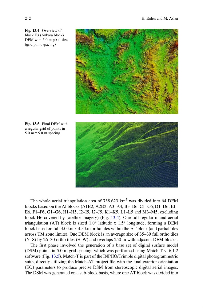
block H6 covered by satellite imagery) (Fig. 13.4). One full regular inland aerial
triangulation (AT) block is sized 1.0
latitude x 1.5
longitude, forming a DEM
block based on full 3.0 km x 4.5 km ortho tiles within the AT block (and partial tiles
across TM zone limits). One DEM block is an average size of 35–39 full ortho tiles
(N–S) by 26–30 ortho tiles (E–W) and overlaps 250 m with adjacent DEM blocks.
The first phase involved the generation of a base set of digital surface model
(DSM) points in 5.0 m grid spacing, which was performed using Match-T v. 6.1.2
software (Fig. 13.5). Match-T is part of the INPHO/Trimble digital photogrammetric
suite, directly utilizing the Match-AT project file with the final exterior orientation
(EO) parameters to produce precise DSM from stereoscopic digital aerial images.
The DSM was generated on a sub-block basis, where one AT block was divided into
Fig. 13.4 Overview of
block E3 (Ankara block)
DEM with 5.0 m pixel size
(grid point spacing)
Fig. 13.5 Final DEM with
a regular grid of points in
5.0 m x 5.0 m spacing
242
H. Erden and M. Aslan
2 was divided into 64 DEM
blocks based on the AI blocks (A1B2, A2B2, A3–A4, B3–B6, C1–C6, D1–D6, E1–
E6, F1–F6, G1–G6, H1–H5, I2–I5, J2–J5, K1–K5, L1–L5 and M3–M5, excluding
block H6 covered by satellite imagery) (Fig. 13.4). One full regular inland aerial
triangulation (AT) block is sized 1.0
latitude x 1.5
longitude, forming a DEM
block based on full 3.0 km x 4.5 km ortho tiles within the AT block (and partial tiles
across TM zone limits). One DEM block is an average size of 35–39 full ortho tiles
(N–S) by 26–30 ortho tiles (E–W) and overlaps 250 m with adjacent DEM blocks.
The first phase involved the generation of a base set of digital surface model
(DSM) points in 5.0 m grid spacing, which was performed using Match-T v. 6.1.2
software (Fig. 13.5). Match-T is part of the INPHO/Trimble digital photogrammetric
suite, directly utilizing the Match-AT project file with the final exterior orientation
(EO) parameters to produce precise DSM from stereoscopic digital aerial images.
The DSM was generated on a sub-block basis, where one AT block was divided into
Fig. 13.4 Overview of
block E3 (Ankara block)
DEM with 5.0 m pixel size
(grid point spacing)
Fig. 13.5 Final DEM with
a regular grid of points in
5.0 m x 5.0 m spacing
242
H. Erden and M. Aslan