

7.7. DIRECTIONAL (3-D) WAVE GENERATION
429
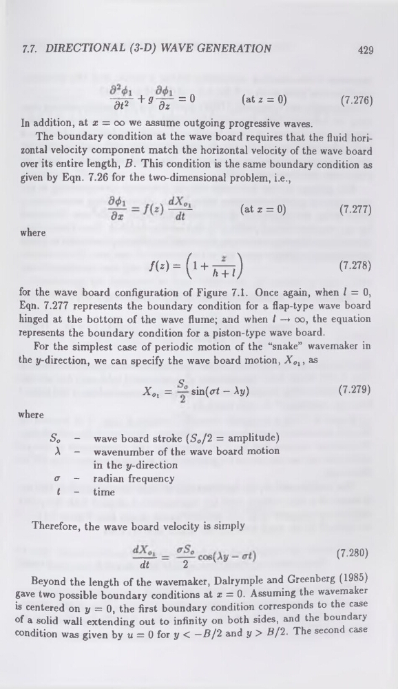
~d^~ + 9~d7 = a
( * t *
= 0)
(7.276)
In addition, at x = oo we assume outgoing progressive waves.
The boundary condition at the wave board requires that the fluid horizontal velocity component match the horizontal velocity of the wave board
over its entire length, B. This condition is the same boundary condition as
given by Eqn. 7.26 for the two-dimensional problem, i.e.,
(at 1 = °)
(7-277)
where
f(z) = (1 + 777)
<7-278)
y h + I )
for the wave board configuration of Figure 7.1. Once again, when / = 0,
Eqn. 7.277 represents the boundary condition for a flap-type wave board
hinged at the bottom of the wave flume; and when I —♦ 00, the equation
represents the boundary condition for a piston-type wave board.
For the simplest case of periodic motion of the “snake” wavemaker in
the y-direction, we can specify the wave board motion, X01, as
Q
XOl =
sin( (7.279)
where
So - wave board stroke (So/Ï = amplitude)
A - wavenumber of the wave board motion
in the y-direction
Therefore, the wave board velocity is simply
C7.280)
dt
2
' *
Beyond the length of the wavemaker, Dalrymple and Greenberg (1985)
gave two possible boundary conditions at x = 0. Assuming the wavemaker
is centered on y = 0, the first boundary condition corresponds to the case
of a solid wall extending out to infinity on both sides, and the boundary
condition was given by u = 0 for y < —5/2 and y > 5/2. The second case
429
~d^~ + 9~d7 = a
( * t *
= 0)
(7.276)
In addition, at x = oo we assume outgoing progressive waves.
The boundary condition at the wave board requires that the fluid horizontal velocity component match the horizontal velocity of the wave board
over its entire length, B. This condition is the same boundary condition as
given by Eqn. 7.26 for the two-dimensional problem, i.e.,
(at 1 = °)
(7-277)
where
f(z) = (1 + 777)
<7-278)
y h + I )
for the wave board configuration of Figure 7.1. Once again, when / = 0,
Eqn. 7.277 represents the boundary condition for a flap-type wave board
hinged at the bottom of the wave flume; and when I —♦ 00, the equation
represents the boundary condition for a piston-type wave board.
For the simplest case of periodic motion of the “snake” wavemaker in
the y-direction, we can specify the wave board motion, X01, as
Q
XOl =
sin( (7.279)
where
So - wave board stroke (So/Ï = amplitude)
A - wavenumber of the wave board motion
in the y-direction
Therefore, the wave board velocity is simply
C7.280)
dt
2
' *
Beyond the length of the wavemaker, Dalrymple and Greenberg (1985)
gave two possible boundary conditions at x = 0. Assuming the wavemaker
is centered on y = 0, the first boundary condition corresponds to the case
of a solid wall extending out to infinity on both sides, and the boundary
condition was given by u = 0 for y < —5/2 and y > 5/2. The second case