

7.3. FIRST-ORDER WAVE GENERATION
361
use identities to express the trigonometric functions in terms of 2at. Next
differentiate Eqn. 7.104 with respect to t and set the result equal to zero. We
can then solve for (2
(T3so)max — Pr + Jp2 r + P'}
The mean wave board power over a wave cycle is
1 / * +T/2
Po — z; I
P0(t)dt
1 J-T/2
(7.105)
(7.106)
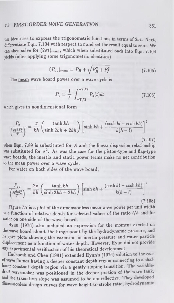
which gives in nondimensional form
Po
_ 7F /
tanhfc/i
\ .
(cosh kl - cosh kh) ' 2
kh \sinh 2kh + 2khJ Sm
k(h — /)
(7.107)
when Eqn. 7.89 is substituted for A and the linear dispersion relationship
was substituted for a2. As was the case for the piston-type and flap-type
wave boards, the inertia and static power terms make no net contribution
to the mean power over a wave cycle.
For water on both sides of the wave board,
_ 2
Poo
2ir (
tanhfch
\ . , ,, , (cosh kl ~ cos^
/P9^s2 a \ kh \sinh 2kh + 2kh J
* ("
‘)
T '
(7.108)
Figure 7.7 is a plot of the dimensionless mean wave power per unit width
as a function of relative depth for selected values of the ratio l/h an or
water on one side of the wave board.
Hyun (1976) also included an expression for the moment exerted on
the wave board about the hinge point by the hydrodynamic pressure, an
he gave plots showing the variation in inertia pressure and water partie e
displacement as a function of water depth. However, Hyun did not provi
any experimental verification of his theoretical development.
Hudspeth and Chen (1981) extended Hyun’s (1976) solution to the case
of wave flumes having a deeper constant depth region connecting to a s
lower constant depth region via a gently sloping transition.
e varia
draft wavemaker was positioned in the deeper portion of the wave
,
and the transition slope was assumed to be nonreflective. T ey e
P
dimensionless design curves for wave height-to-stroke ratio, yr y
361
use identities to express the trigonometric functions in terms of 2at. Next
differentiate Eqn. 7.104 with respect to t and set the result equal to zero. We
can then solve for (2
(T3so)max — Pr + Jp2 r + P'}
The mean wave board power over a wave cycle is
1 / * +T/2
Po — z; I
P0(t)dt
1 J-T/2
(7.105)
(7.106)
which gives in nondimensional form
Po
_ 7F /
tanhfc/i
\ .
(cosh kl - cosh kh) ' 2
kh \sinh 2kh + 2khJ Sm
k(h — /)
(7.107)
when Eqn. 7.89 is substituted for A and the linear dispersion relationship
was substituted for a2. As was the case for the piston-type and flap-type
wave boards, the inertia and static power terms make no net contribution
to the mean power over a wave cycle.
For water on both sides of the wave board,
_ 2
Poo
2ir (
tanhfch
\ . , ,, , (cosh kl ~ cos^
/P9^s2 a \ kh \sinh 2kh + 2kh J
* ("
‘)
T '
(7.108)
Figure 7.7 is a plot of the dimensionless mean wave power per unit width
as a function of relative depth for selected values of the ratio l/h an or
water on one side of the wave board.
Hyun (1976) also included an expression for the moment exerted on
the wave board about the hinge point by the hydrodynamic pressure, an
he gave plots showing the variation in inertia pressure and water partie e
displacement as a function of water depth. However, Hyun did not provi
any experimental verification of his theoretical development.
Hudspeth and Chen (1981) extended Hyun’s (1976) solution to the case
of wave flumes having a deeper constant depth region connecting to a s
lower constant depth region via a gently sloping transition.
e varia
draft wavemaker was positioned in the deeper portion of the wave
,
and the transition slope was assumed to be nonreflective. T ey e
P
dimensionless design curves for wave height-to-stroke ratio, yr y