

8. Design of Coastal Structures
247
where Ld is the wavelength where the water depth is equal to da, m is the
nearshore slope. The triangular hydrostatic pressure distribution is shown
in Fig. 8.11, the pressure is zéro at the breaker crest (taken at Hb/2 above
SWL), and increases linearly to y(ds + Hb/2) at the toe of the wall. The
total breaking wave force on the wall per unit length is
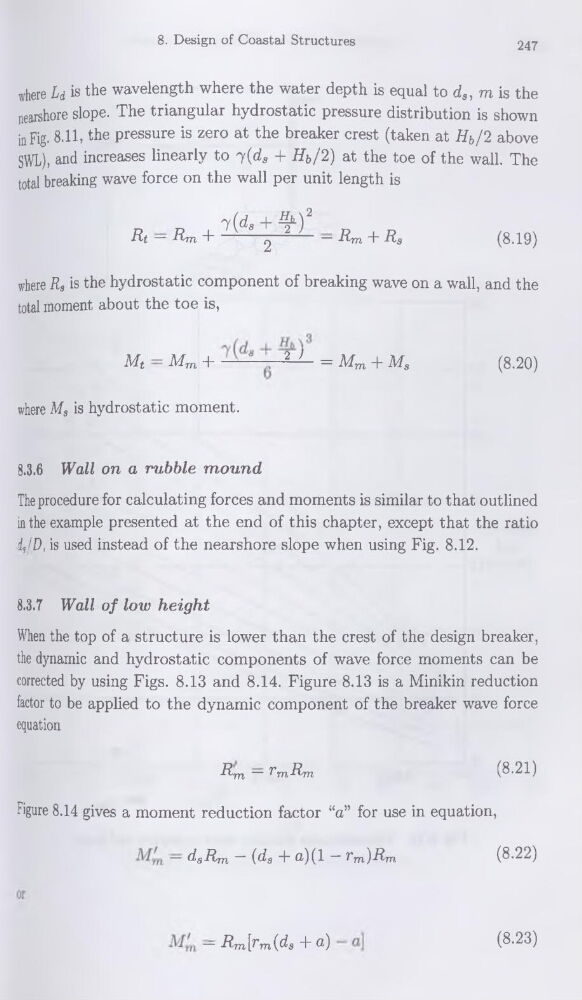
Rt — Rm +
— Rm + Rs
(8.19)
where Rs is the hydrostatic component of breaking wave on a wall, and the
total moment about the toe is,
Mt — Mm +
-, 2 7 = Mm + Ms
(8.20)
where Ms is hydrostatic moment.
8.3.6 Wall on a rubble mound
The procedure for calculating forces and moments is similar to that outlined
in the example presented at the end of this chapter, except that the ratio
ds/D, is used instead of the nearshore slope when using Fig. 8.12.
8.3.7 Wall of low height
When the top of a structure is lower than the crest of the design breaker,
the dynamic and hydrostatic components of wave force moments can be
corrected by using Figs. 8.13 and 8.14. Figure 8.13 is a Minikin réduction
factor to be applied to the dynamic component of the breaker wave force
équation
Rm — TmRm
(8-21)
Figure 8.14 gives a moment réduction factor “a” for use in équation,
— dsRm ~' (ds T a)(l ~ rm')Rm
(8.22)
— Rm[^m{ds T ®)
(8.23)
247
where Ld is the wavelength where the water depth is equal to da, m is the
nearshore slope. The triangular hydrostatic pressure distribution is shown
in Fig. 8.11, the pressure is zéro at the breaker crest (taken at Hb/2 above
SWL), and increases linearly to y(ds + Hb/2) at the toe of the wall. The
total breaking wave force on the wall per unit length is
Rt — Rm +
— Rm + Rs
(8.19)
where Rs is the hydrostatic component of breaking wave on a wall, and the
total moment about the toe is,
Mt — Mm +
-, 2 7 = Mm + Ms
(8.20)
where Ms is hydrostatic moment.
8.3.6 Wall on a rubble mound
The procedure for calculating forces and moments is similar to that outlined
in the example presented at the end of this chapter, except that the ratio
ds/D, is used instead of the nearshore slope when using Fig. 8.12.
8.3.7 Wall of low height
When the top of a structure is lower than the crest of the design breaker,
the dynamic and hydrostatic components of wave force moments can be
corrected by using Figs. 8.13 and 8.14. Figure 8.13 is a Minikin réduction
factor to be applied to the dynamic component of the breaker wave force
équation
Rm — TmRm
(8-21)
Figure 8.14 gives a moment réduction factor “a” for use in équation,
— dsRm ~' (ds T a)(l ~ rm')Rm
(8.22)
— Rm[^m{ds T ®)
(8.23)