

8. Design of Coastal Structures
237
\tiche-Rundgren (1958)
vliche-Rundgren method of wave force estimation is based on the modfied Sainflou’s formula (1928). Non-breaking waves incident on smooth.
mpermeable vertical walls are completely reflected by the wall with a
■eflection coefficient of 1.0. Vertical walls built on rubble bases commonly
idopted as toe protection or in the case of composite breakwaters will expe•ience lesser reflection coefficient and hence reduced forces. For complété
details on the wave forces on wall type structures one can also refer to CEM
(2002).
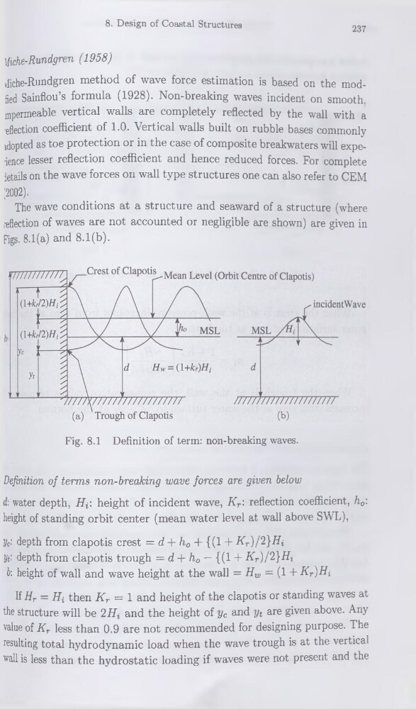
The wave conditions at a structure and seaward of a structure (where
reflection of waves are not accounted or negligible are shown) are given in
Figs. 8.1(a) and 8.1(b).
Fig. 8.1 Définition of term: non-breaking waves.
Définition of terms non-breaking wave forces are given below
d: water depth, Hf. height of incident wave, Kr: reflection coefficient, h0:
height of standing orbit center (mean water level at wall above SWL),
yc‘ depth from clapotis crest = d + h0 + {(1 + Kr)/2}Hi
yt' depth from clapotis trough = d + h0 — {(1 + Kr}/2}Hl
b: height of wall and wave height at the wall = Hw = (1 + Kr)Hi
If Hr = Hi then Kr = 1 and height of the clapotis or standing waves at
the structure will be 2HZ and the height of yc and yt are given above. Any
value of Kr less than 0.9 are not recommended for designing purpose. The
resulting total hydrodynamic load when the wave trough is at the vertical
wall is less than the hydrostatic loading if waves were not présent and the
237
\tiche-Rundgren (1958)
vliche-Rundgren method of wave force estimation is based on the modfied Sainflou’s formula (1928). Non-breaking waves incident on smooth.
mpermeable vertical walls are completely reflected by the wall with a
■eflection coefficient of 1.0. Vertical walls built on rubble bases commonly
idopted as toe protection or in the case of composite breakwaters will expe•ience lesser reflection coefficient and hence reduced forces. For complété
details on the wave forces on wall type structures one can also refer to CEM
(2002).
The wave conditions at a structure and seaward of a structure (where
reflection of waves are not accounted or negligible are shown) are given in
Figs. 8.1(a) and 8.1(b).
Fig. 8.1 Définition of term: non-breaking waves.
Définition of terms non-breaking wave forces are given below
d: water depth, Hf. height of incident wave, Kr: reflection coefficient, h0:
height of standing orbit center (mean water level at wall above SWL),
yc‘ depth from clapotis crest = d + h0 + {(1 + Kr)/2}Hi
yt' depth from clapotis trough = d + h0 — {(1 + Kr}/2}Hl
b: height of wall and wave height at the wall = Hw = (1 + Kr)Hi
If Hr = Hi then Kr = 1 and height of the clapotis or standing waves at
the structure will be 2HZ and the height of yc and yt are given above. Any
value of Kr less than 0.9 are not recommended for designing purpose. The
resulting total hydrodynamic load when the wave trough is at the vertical
wall is less than the hydrostatic loading if waves were not présent and the