

200
Coastal Engineering: Theory and Practice
Or is the wave incidence réduction factor. This translates into using Df
only when Df > 0.3, and using (DfOr) when Df < 0.3.
For roughened slopes or those incorporating a berm, Besley [1999] recommends the détermination of a smooth slope that gives the same overtopping discharge at the top of the slope, for the same wave conditions.
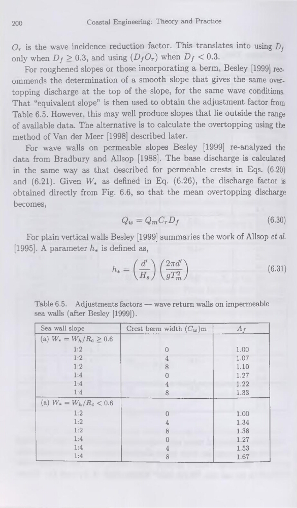
That “équivalent slope” is then used to obtain the adjustment factor from
Table 6.5. However, this may well produce slopes that lie outside the range
of available data. The alternative is to calculate the overtopping using the
method of Van der Meer [1998] described later.
For wave walls on permeable slopes Besley [1999] re-analyzed the
data from Bradbury and Allsop [1988]. The base discharge is calculated
in the same way as that described for permeable crests in Eqs. (6.20)
and (6.21). Given VF* as defined in Eq. (6.26), the discharge factor is
obtained directly from Fig. 6.6, so that the mean overtopping discharge
becomes,
Qu — Qm.C'rDf
(6.30)
For plain vertical walls Besley [1999] summaries the work of Allsop et al.
[1995]. A parameter h* is defined as,
(6.31)
Table 6.5. Adjustments factors — wave return walls on imperméable
sea walls (after Besley [1999]).
Sea wall slope
Crest berm width (Cw)m
Af
(a) W, = Wh/Rc > 0.6
1:2
0
1.00
1:2
4
1.07
1:2
8
1.10
1:4
0
1.27
1:4
4
1.22
1:4
8
1.33
(a) W» = Wh/Rc < 0.6
1:2
0
1.00
1:2
4
1.34
1:2
8
1.38
1:4
0
1.27
1:4
4
1.53
1:4
8
1.67
Coastal Engineering: Theory and Practice
Or is the wave incidence réduction factor. This translates into using Df
only when Df > 0.3, and using (DfOr) when Df < 0.3.
For roughened slopes or those incorporating a berm, Besley [1999] recommends the détermination of a smooth slope that gives the same overtopping discharge at the top of the slope, for the same wave conditions.
That “équivalent slope” is then used to obtain the adjustment factor from
Table 6.5. However, this may well produce slopes that lie outside the range
of available data. The alternative is to calculate the overtopping using the
method of Van der Meer [1998] described later.
For wave walls on permeable slopes Besley [1999] re-analyzed the
data from Bradbury and Allsop [1988]. The base discharge is calculated
in the same way as that described for permeable crests in Eqs. (6.20)
and (6.21). Given VF* as defined in Eq. (6.26), the discharge factor is
obtained directly from Fig. 6.6, so that the mean overtopping discharge
becomes,
Qu — Qm.C'rDf
(6.30)
For plain vertical walls Besley [1999] summaries the work of Allsop et al.
[1995]. A parameter h* is defined as,
(6.31)
Table 6.5. Adjustments factors — wave return walls on imperméable
sea walls (after Besley [1999]).
Sea wall slope
Crest berm width (Cw)m
Af
(a) W, = Wh/Rc > 0.6
1:2
0
1.00
1:2
4
1.07
1:2
8
1.10
1:4
0
1.27
1:4
4
1.22
1:4
8
1.33
(a) W» = Wh/Rc < 0.6
1:2
0
1.00
1:2
4
1.34
1:2
8
1.38
1:4
0
1.27
1:4
4
1.53
1:4
8
1.67