

6. Wave Run-up and Overtopping
197
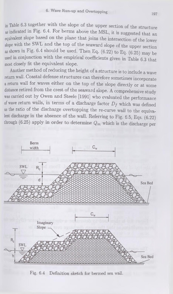
in Table 6.3 together with the slope of the upper section of the structure
as indicated in Fig. 6.4. For berms above the MSL, it is suggested that an
équivalent slope based on the plane that joins the intersection of the lower
slope with the SWL and the top of the seaward slope of the upper section
as shown in Fig. 6.4 should be used. Then Eq. (6.22) to Eq. (6.25) may be
used in conjunction with the empirical coefficients given in Table 6.3 that
most closely fit the équivalent slope.
Another method of reducing the height of a structure is to include a wave
return wall. Coastal defense structures can therefore sometimes incorporate
a return wall for waves either on the top of the slope directly or at some
distance retired from the crest of the seaward slope. A comprehensive study
was carried out by Owen and Steele [1991] who evaluated the performance
ofwave return walls, in terms of a discharge factor Df which was defined
as the ratio of the discharge overtopping the re-curve wall to the équivalent discharge in the absence of the wall. Referring to Fig. 6.5, Eqs. (6.22)
through (6.25) apply in order to détermine Qm which is the discharge per
Berm
width
Fig. 6.4 Définition sketch for bermed sea wall.
197
in Table 6.3 together with the slope of the upper section of the structure
as indicated in Fig. 6.4. For berms above the MSL, it is suggested that an
équivalent slope based on the plane that joins the intersection of the lower
slope with the SWL and the top of the seaward slope of the upper section
as shown in Fig. 6.4 should be used. Then Eq. (6.22) to Eq. (6.25) may be
used in conjunction with the empirical coefficients given in Table 6.3 that
most closely fit the équivalent slope.
Another method of reducing the height of a structure is to include a wave
return wall. Coastal defense structures can therefore sometimes incorporate
a return wall for waves either on the top of the slope directly or at some
distance retired from the crest of the seaward slope. A comprehensive study
was carried out by Owen and Steele [1991] who evaluated the performance
ofwave return walls, in terms of a discharge factor Df which was defined
as the ratio of the discharge overtopping the re-curve wall to the équivalent discharge in the absence of the wall. Referring to Fig. 6.5, Eqs. (6.22)
through (6.25) apply in order to détermine Qm which is the discharge per
Berm
width
Fig. 6.4 Définition sketch for bermed sea wall.