

5. Rubble Mound Structures
179
5.6.4 Results of analysis
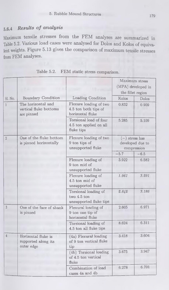
Maximum tensile stresses from the FEM analyses are summarized in
Table 5.2. Varions load cases were analysed for Dolos and Kolos of équivalent weights. Figure 5.13 gives the comparison of maximum tensile stresses
from FEM analyses.
Table 5.2. FEM static stress comparison.
SI. No.
Boundary Condition
Loading Condition
Maximum stress
(MPA) developed in
the fillet région
Kolos
Dolos
1
The horizontal and
vertical fluke bottoms
are pinned
Flexure loading of two
4.5 ton both tips of
horizontal fluke
0.832
0.909
Torsional load of four
4.5 ton applied on ail
fluke tips
5.285
5.109
2
One of the fluke bottom
is pinned horizontally
Flexure loading of two
9 ton tips of
unsupported fluke
(—) stress has
developed due to
compression
-5.7
-6.5
Flexure loading of
9 ton mid of
unsupported fluke
3.922
6.582
Flexure loading of
4.5 ton mid of
unsupported fluke
1.961
3.291
Torsional loading of
two 4.5 ton
unsupported fluke tips
2.842
3.186
3
One of the face of shank
is pinned
Flexural loading of
9 ton one tip of
horizontal fluke
2.605
6.971
Torsional loading of
4.5 ton ail fluke tips
8.624
6.311
4
Horizontal fluke is
supported along its
outer edge
(4a) Flexural loading
of 9 ton vertical fluke
tip
3.418
3.604
(4b) Torsional loading
of 4.5 ton vertical
fluke
3.675
3.947
Combination of load
cases 4a and 4b
6.278
6.701
179
5.6.4 Results of analysis
Maximum tensile stresses from the FEM analyses are summarized in
Table 5.2. Varions load cases were analysed for Dolos and Kolos of équivalent weights. Figure 5.13 gives the comparison of maximum tensile stresses
from FEM analyses.
Table 5.2. FEM static stress comparison.
SI. No.
Boundary Condition
Loading Condition
Maximum stress
(MPA) developed in
the fillet région
Kolos
Dolos
1
The horizontal and
vertical fluke bottoms
are pinned
Flexure loading of two
4.5 ton both tips of
horizontal fluke
0.832
0.909
Torsional load of four
4.5 ton applied on ail
fluke tips
5.285
5.109
2
One of the fluke bottom
is pinned horizontally
Flexure loading of two
9 ton tips of
unsupported fluke
(—) stress has
developed due to
compression
-5.7
-6.5
Flexure loading of
9 ton mid of
unsupported fluke
3.922
6.582
Flexure loading of
4.5 ton mid of
unsupported fluke
1.961
3.291
Torsional loading of
two 4.5 ton
unsupported fluke tips
2.842
3.186
3
One of the face of shank
is pinned
Flexural loading of
9 ton one tip of
horizontal fluke
2.605
6.971
Torsional loading of
4.5 ton ail fluke tips
8.624
6.311
4
Horizontal fluke is
supported along its
outer edge
(4a) Flexural loading
of 9 ton vertical fluke
tip
3.418
3.604
(4b) Torsional loading
of 4.5 ton vertical
fluke
3.675
3.947
Combination of load
cases 4a and 4b
6.278
6.701