

No — Damage Criteria and Minor Overtopping
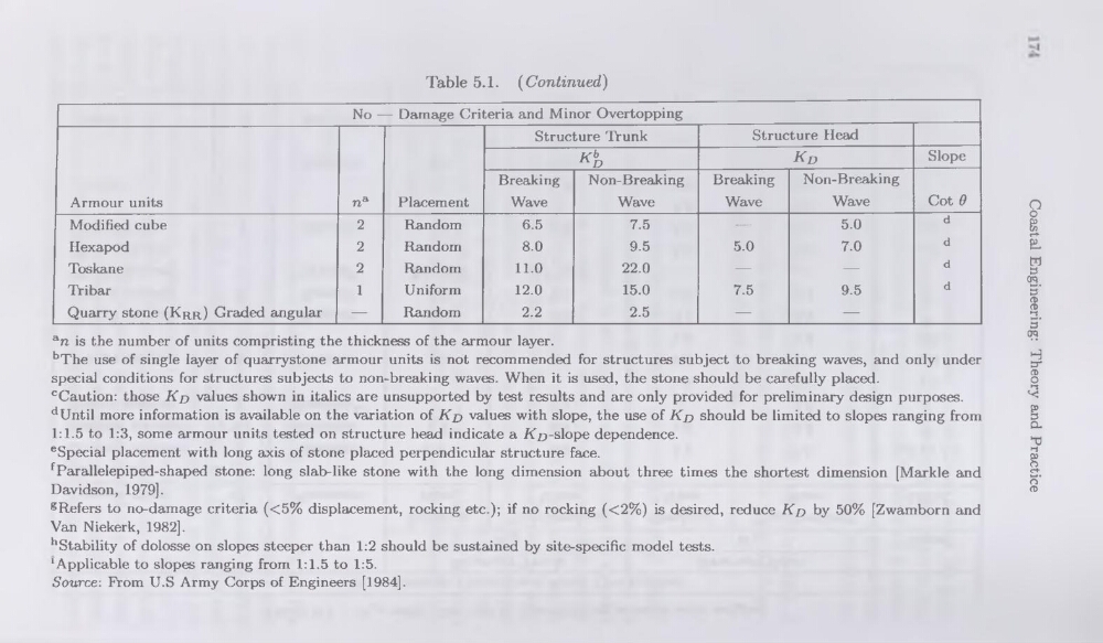
Table 5.1. (Continued)
Armour units
na
Placement
Structure Trunk
Structure Head
Kb
n-D
Kd
Slope
Breaking
Wave
Non-Breaking
Wave
Breaking
Wave
Non-Breaking
Wave
Cot d
Modified cube
2
Random
6.5
7.5
—
5.0
d
Hexapod
2
Random
8.0
9.5
5.0
7.0
d
Toskane
2
Random
11.0
22.0
—
—
d
Tri bar
1
Uniform
12.0
15.0
7.5
9.5
d
Quarry stone (Krr) Graded angular
—
Random
2.2
2.5
—
—
an is the number of units compristing the thickness of the armour layer.
bThe use of single layer of quarrystone armour units is not recommended for structures subject to breaking waves, and only under
spécial conditions for structures subjects to non-breaking waves. When it is used, the stone should be carefully placed.
cCaution: those Kd values shown in italics are unsupported by test results and are only provided for preliminary design purposes.
dUntil more information is available on the variation of Kd values with slope, the use of Kd should be limited to slopes ranging from
1:1.5 to 1:3, some armour units tested on structure head indicate a 7<£)-slope dependence.
eSpecial placement with long axis of stone placed perpendicular structure face.
fParallelepiped-shaped stone: long slab-like stone with the long dimension about three times the shortest dimension [Markle and
Davidson, 1979].
gRefers to no-damage criteria (<5% displacement, rocking etc.); if no rocking (<2%) is desired, reduce Kd by 50% [Zwamborn and
Van Niekerk, 1982],
hStability of dolosse on slopes steeper than 1:2 should be sustained by site-specific model tests.
'Applicable to slopes ranging from 1:1.5 to 1:5.
Source: From U.S Army Corps of Engineers [1984].
Coastal Engineering: Theory and Practice
Table 5.1. (Continued)
Armour units
na
Placement
Structure Trunk
Structure Head
Kb
n-D
Kd
Slope
Breaking
Wave
Non-Breaking
Wave
Breaking
Wave
Non-Breaking
Wave
Cot d
Modified cube
2
Random
6.5
7.5
—
5.0
d
Hexapod
2
Random
8.0
9.5
5.0
7.0
d
Toskane
2
Random
11.0
22.0
—
—
d
Tri bar
1
Uniform
12.0
15.0
7.5
9.5
d
Quarry stone (Krr) Graded angular
—
Random
2.2
2.5
—
—
an is the number of units compristing the thickness of the armour layer.
bThe use of single layer of quarrystone armour units is not recommended for structures subject to breaking waves, and only under
spécial conditions for structures subjects to non-breaking waves. When it is used, the stone should be carefully placed.
cCaution: those Kd values shown in italics are unsupported by test results and are only provided for preliminary design purposes.
dUntil more information is available on the variation of Kd values with slope, the use of Kd should be limited to slopes ranging from
1:1.5 to 1:3, some armour units tested on structure head indicate a 7<£)-slope dependence.
eSpecial placement with long axis of stone placed perpendicular structure face.
fParallelepiped-shaped stone: long slab-like stone with the long dimension about three times the shortest dimension [Markle and
Davidson, 1979].
gRefers to no-damage criteria (<5% displacement, rocking etc.); if no rocking (<2%) is desired, reduce Kd by 50% [Zwamborn and
Van Niekerk, 1982],
hStability of dolosse on slopes steeper than 1:2 should be sustained by site-specific model tests.
'Applicable to slopes ranging from 1:1.5 to 1:5.
Source: From U.S Army Corps of Engineers [1984].
Coastal Engineering: Theory and Practice